Archive through February 24, 2007
|
New member Username: SkslvnvPost Number: 10 Registered: Mar-06 | Glad you finally got it Sally... persistence pays off! Also, thanks for the kind words... Brian, if you are seeing a line across the picture on any projection TV, the results can be permanent damage to the CRT's and render the set not economical to repair. All projection sets are designed to shut-off in the event of a sweep failure and that is what you are describing. It's possible that CRT coolant leakage is the cause of this failure. I would advise that you don't turn it on again and call a professional. I'm sorry, but this is one where the stakes are high at making the problem worse by messing with it. | |
|
New member Username: BrianinrowlettRowlett, TX Post Number: 2 Registered: Oct-06 | Thanks, SKSLVNV. Plan to do so. Not very good a soldering anyway. | |
|
New member Username: GusmanPost Number: 1 Registered: Oct-06 | Hey everyone, I've been reading thru the posts and have found them very informative. I have a Toshiba 50h72 that is about 5 yrs old, last week I began having what I now think is a convergence problem because i can't align the colors. when i'm in the service menu i can adjust the red but the blue does not respond and is bending almost curving to the bottom right. I think I can replace the convergence ic's and have already located them inside the set. But I have never worked on a tv before (lots of pcs and other such stuff) and I remember an old timer telling me never to open the back of a tv as I could wake up in heaven. Do i need to drain the caps? if thats what you call it, and if so, how? thanks | |
|
Bronze Member Username: SkslvnvPost Number: 11 Registered: Mar-06 | There are no "caps" to drain on any television. The stored power you are referring to is in the CRT's (picture tubes) themselves and for most projection TV's, the charge is drained back through the HV divider network when you turn the set off. On single CRT sets with a high voltage lead going into the side of the CRT, you can short the HV lead to ground to discharge the CRT, but you should NEVER do that on ANY projection set. Let me repeat... NEVER. Your problem is most likely caused by a defective convergence amplifier IC similar to these Mitsubishis. You need to have better than average soldering skills to try any of these types of repairs. Finally, there is nothing inside of any television that would kill anyone under normal circumstances, off or on. At some point, every technician needs to be able to work on a set that has power applied, but for the most part, if you do your work with the power unplugged, there is no danger of getting anything worse than the static discharge you get from new carpet. | |
|
New member Username: Sally_bodyPost Number: 7 Registered: Oct-06 | SKSLVNV ,yes you are correct on the crt discharging from the hv block. i could not get any discharging of the crt,s hv wire after letting it sit all night,however i have been hit with a crt and i would say it is worse then a static shock L.O.L also you a correct not to discharge crts to ground, due to a cold and hot ground,you can fry the set discharging 30k to hot ground. the proper way is to ground the metal on the crt which should be negetive polarity and to the hv block should be the same as discharging a cap with out inducing any hv to circuitry,correct me if i'm wrong |
|
|
New member Username: GusmanPost Number: 2 Registered: Oct-06 | thanks for the info | |
|
New member Username: BradsterPost Number: 1 Registered: Oct-06 | Hello everyone. I've been reading all of the posts and I'm excited there's a possibility I can fix my Mitsubishi WS65807 without calling a repair person. My problem with the "bow tie" is that it starts when the TV is first turned on and usually goes away after about 15 -30 minutes, but sometimes it'll take hours. Sometimes a Fonzie (I'll hit the top or side of the cabinet) will fix the problem but I know hitting the Tv isn't the solution. I have good soldering skills and would appreciate any advice. Thanks! |
|
|
New member Username: BradsterPost Number: 2 Registered: Oct-06 | Hello everyone. I've been reading all of the posts and I'm excited there's a possibility I can fix my Mitsubishi WS65807 without calling a repair person. My problem with the "bow tie" is that it starts when the TV is first turned on and usually goes away after about 15 -30 minutes, but sometimes it'll take hours. Sometimes a Fonzie (I'll hit the top or side of the cabinet) will fix the problem but I know hitting the Tv isn't the solution. I have good soldering skills and would appreciate any advice. Thanks! |
|
|
Bronze Member Username: MickeynguyenTallahassee, FL USA Post Number: 11 Registered: Jul-06 | Hello BW, That was exactly my problem too. It's the classic conevergence IC problems. Replace the two (2) convergence ship should fix your problem. There are plenty of good posts here on how to do it. Just be patience during the de-soldering process and you should be fine. Remember to mark all the connectors when you remove the board. The board that have the convergence IC (STK392-570) should the middle board with the large heat sink on the ICs. I highly recommend changing both of the chips. Make sure you clean off the old heat sink paste and apply new paste (just a thin film would do the trick). Good luck, My TV have been working great for 3-4 months now since the repair. |
|
|
New member Username: Sally_bodyPost Number: 8 Registered: Oct-06 | I have a power board already to go with stk392-570 replaced(factory chips not after market) and tested. Power board part number is 930B867001 for a WS-65907 Mitsubishi rear projector.(keep your heat sink for the stk"s.) I am asking $ 175.00 with your old board as long as it has not been damage by repair attempts. I am in upstate New York. Please only serious people reply ,pm me. and we can discuss exchange of parts and secured funds. Thank you Sally |
|
|
New member Username: 05evoPost Number: 1 Registered: Oct-06 | I am glad I found this forum and post. I bought a WS-55809 probably about 5 years ago when they first came out. I tweak everything in my life, from my computers, to cars, to TVs. For my TV, I found a forum (hometheaterspot.com - that is now a pay site for the good stuff) that had the service manual codes and I was able to calibrate my TV pretty well. Anyway, to make a long story short, I am getting the bowtie effect of the IC chips going bad. If I turn the TV off for a minute or so, everything is fine for a while. It seems to be happening more frequently over the last couple of weeks. What I am writing here for is if someone could email me the service manual for the WS-55809. I have read this whole thread and it looks like there are a bunch of nice people here. Hopefully someone can help me out. Thanks, Eric |
|
|
New member Username: BroncoPost Number: 1 Registered: Oct-06 | I have a VS 60803 Mits. that has no picture. There is sound and I replaced the stk 392-040 ICs. I would really be greatful for any help that I can get. | |
|
New member Username: Bsarno18Post Number: 1 Registered: Oct-06 | I have the WS-55809 and last week this POS started doing the same hour glass effect. I am going to try and fix it myself by replacing the 2 convergance chips that are mentioned in all these detailed posts. Does anybody have the service manual that can be emailed to me? Also it looks like I need to purchace two STK392-570 chips and heat sink paste to do the fix. Someone correct me if I am wrong. Thanks |
|
|
Bronze Member Username: SkslvnvPost Number: 12 Registered: Mar-06 | Bryan, The service manual is too large to send via email and it doesn't help you in any way to replace these parts. If you really want the service manual, you can buy a copy on eBay, but unless you're a TV technician, it won't be of any help. 99% of the time, replacing the IC's fixes the problem. If you've let the problem go on so long that the set no longer comes on, then you will need to do further troubleshooting. If you want the one page info sheet I've put together, send me an email. Steve |
|
|
New member Username: BrianinrowlettRowlett, TX Post Number: 3 Registered: Oct-06 | To: SKSLVNV Just wanted to thank you for the accurate advice. Techician just left. Confirmed that the blue tube had leaked onto the board. $$$$ to fix. Am now in the market for a DLP. BTW for anyone in the DFW area, Har-West is a good repair outfit. |
|
|
New member Username: GusmanPost Number: 3 Registered: Oct-06 | I replaced the the 2 convergence ic but I still have a horizontal hourglass effect on the blue and when I try to do the convergence I can only move the blue left and right not up and down, any ideas? | |
|
New member Username: Andy57sJackson, New Jersey USA Post Number: 8 Registered: Jul-06 | Gus, I had the same problem with my Mitsu after changing the Convergence Chips, See Below: Problem: Started having the convergence problem on my VS-45609. Had the same thing happen 2 years ago, but under warranty. At first is was intermittent, after the set heated up, now the Blue is always off (Bow-tie Affect). Solution: I received the Mitsubishi STK393-110 (Yes, I paid extra for the Mitsu Part) and installed it today. Everything went fine, but it didn't fix the problem. It is exactly as before Blue Bowtie effect. Swapped the 4 pin connectors that go to the green & blue. The green bowtied, blue was OK, proving the Convergence Blue circuitry was not working between the STK chip and the Guns. Decided to measure the 4 pin connectors to GRD. Blue was higher resistance on 2 of pins than the red/green. Measured components, they were OK. Connector VU had cracked joints. Checked all the other thru-hole connectors, at least one cracked joint per connector. Resoldered every Thru-Hole connector. TV picture is back to normal. I owe a lot to SteveLVNV, He is the Expert and helped me through all the diagnosis. Moral, replace STK & touch up ALL solder joints (especially connectors) on these TV's Thx to all, Andy |
|
|
New member Username: GuykinleyPost Number: 1 Registered: Nov-06 | I have a Mitsubishi VS-45605, and it works great. Only problem is that the Diamond Shield is cracked. I can get a replacement from Mitsu for ~$100, but I don't know how to install it. The local tech wants $500 after estimate, labor and parts, and the TV just isn't worth that these days. Any advice on how to remove the bezel or housing? Its not obvious to me. | |
|
Bronze Member Username: SkslvnvPost Number: 13 Registered: Mar-06 | First things first, let's make sure that you are wanting to replace the OUTER, smooth-surfaced, protection screen that covers the inner screens. The inner screens have fine ridges cut into them and have a rough surface. If either or both of the inner screens (technically called the lenticular and fresnel lenses) are damaged, don't waste your money on the diamond shield, because the inner lenses are no longer available. If you are replacing the diamond shield simply because it is scratched, you do NOT remove the frame to replace it. The part comes with instructions on how to replace. Basically, there are four trim pieces that go around the inside edge of the frame. Once removed, you usually have to flex the shield outward in the middle to remove, then reverse the procedure to replace. Always use clean cotton gloves when handing the lenses or shields. By the way, if you don't have small children or animals that could potentially damage the screen surface, the set works just fine without the diamond shield. In fact, you will notice improved brightness with the shield removed because it is tinted dark to reduce glare. They made sets for years without protection shields, so it's no big deal. | |
|
New member Username: GuykinleyPost Number: 3 Registered: Nov-06 | My first, viewer-facing screen has fine vertical ridges. So I take it that my set does not have a Diamond Shield and that my kids have cracked one of the two irreplaceable lens. Is that the gist of it? If so, and they are so easy to crack, why on earth would a company like Mitsubishi stop making a key $100 part for a box that costs $1000s? |
|
|
Bronze Member Username: SkslvnvPost Number: 14 Registered: Mar-06 | Guy, When I checked the parts list for your model, it showed no listing for the lenticular (outer) lens, which usually indicates that the part is NLA. The fresnel (inner) lens is listed and is definitely NLA. However, I am showing availablility on the lenticular, even though it's not in the main parts list. You will need to contact the Mitsubishi parts department at 1-800-553-7278 and see if they do in fact have it. I believe the part number is 491P075010. Also, the part lists for $183.10 plus shipping. Remember, this is not just a piece of plastic, but a highly critical, machine-cut lens. I believe they can only be shipped via truck, so it will probably cost over $200. The replacement instructions are usually included with the part. If not, send me an email and I will send you what I have. Steve | |
|
New member Username: Keith1319Post Number: 1 Registered: Nov-06 | I am desperately in need of a circuit board for my 60 inch TV. Model # VS60609. I think the part number is 930B875001 ASSY-PWB-SIGNAL Mine broke while trying to repace the convergence adapter. Can someone PLEASE point me in the right direction? I tried on ebay, ubid etc, but no luck. I even contacted Mitsubishi and was told they no longer make that part!!! ANY HELP WOULD BE APPRECIATED. |
|
|
Bronze Member Username: CrashnashPost Number: 49 Registered: Jul-06 | Keith--just a suggestion. Try PTS Electronis at 800 844-7871 CrashNash |
|
|
New member Username: MinskiOrange, California USA Post Number: 3 Registered: Nov-06 | Hello everyone, I own a WS-65809 had a power up problem. Call service out and after $350.00, problem solved. He changed 2 ICs... But now I have a new problem. After the tech left, I watched the TV that night and noticed the lower left corner of the TV is blurry and the green is bleeding in the background. Tried to do advance adjustment on the set, but noticed only 2 colors appear.. red and blue... is there a "green" color that I am missing? Did the tech forget to plug something back in?? I called the tech and he said it's a different problem and will charge me to come out. Is there a fix for this?? Thank you in advance... |
|
|
Bronze Member Username: SkslvnvPost Number: 15 Registered: Mar-06 | I can help, but I need to know which IC's were replaced. Can you give me the part numbers? Also, if you want to take a digital photo of the symptom and email it directly to me, I can give you my opinion if the new problem is related to the original one. | |
|
New member Username: GmacePost Number: 3 Registered: Nov-06 | Looking for a service manual and schematic for my Mistsubishi WS-55807. Any help is greatly appreciated. I need to replace my convergenace chips and want to install a cooling fan. Anyone resolder and have fixed the convergence chip problems? |
|
|
New member Username: JoshicarterPost Number: 1 Registered: Nov-06 | need help with set I have a WS65809 mit and i am having the same hour glass problem will the STK392-570 IC work for my model and which part munber for the fuses |
|
|
New member Username: Bsarno18Post Number: 2 Registered: Oct-06 | Steve or anyone else on this board, I am hoping you can help provide some insight to one issue I am experiencing. While disconnecting all of the wires/connectors from the chassis, I was having some difficulties removing the white wire from the part labeled FBT on the chassis. This is this the part that is located in the front right hand corner of the chassis. Thinking that the wire harness was a snap removal like the rest of them, I pulled the white wire out of the "FBT" and I think I shouldn't have done that. It looks like the wire might of broke off to something inside of the FBT. Are you familiar with this part? Do you think I damaged the part beyond repair? Do you know what the FBT part # is, I can't find it listed any where in the manual except for this diagram you have provided from the service manual. Please let me know if you are familar with this part. I am trying to gauge an idea of damage I did by removing this wire from the FBT part. It looks like the entire FBT unit is soldered onto the main board so if it can't be fixed, I will just bring the entire board to the TV shop. Thanks, Bryan |
|
|
Bronze Member Username: SkslvnvPost Number: 16 Registered: Mar-06 | Bryan, The FBT is the flyback transformer. I'm not certain on Mitsubishi's design if you can re-install the wire back into the transformer once it's removed. All I can suggest is to strip back about 1/8" of insulation, make sure the wire is straight and try to push it back inside the hole where the wire came out of. Many flyback transformers have a wire capture clamp that grabs on to the wire when inserted. If you're lucky, it will re-grab and you'll be ok. Be sure to pull on the wire slightly to be certain that it has re-attached. If this doesn't work, you may have to replace the transformer. Try it and let me know the results. |
|
|
New member Username: Bsarno18Post Number: 3 Registered: Oct-06 | Steve, I think I will need to install a new flyback transformer. I can still see some pieces of wire at the bottom of the hole in the transformer. I have a few part #'s from the manual (T5A51 and 334P278010) but I cant seem to find this part anywhere like MCM electronics. Do you know where I can buy one of these FBT's? |
|
|
Bronze Member Username: SkslvnvPost Number: 17 Registered: Mar-06 | Bryan, Mitsubishi is the only source for your part. The part number is 334P278010 and it appears to be in stock. Cost is $45.30 plus shipping. You can reach Mitsubishi parts at 1-800-553-7278 and order by credit card. My email address is changed, but if you need to, email me through the forum. Steve |
|
|
New member Username: Bsarno18Post Number: 4 Registered: Oct-06 | Steve, I brought the main board to a TV Tech and he was able to save the FBT. He told me he had some very small needle nose plyers and was able to pull out the remaining wire strands from the clamp. Once he cleared the clamp, he was then able to restrip the wire and reinsert the wire saving me 50 bucks. I also had him install the 2 new IC's onto the board. But I was wondering do I need to go through the convergance menu and converge the TV all over again because of the 2 new IC's. If I reset to factory defaults will that converage the TV or do I need to go through the advanced settings in the manual. Thanks, Bryan |
|
|
Bronze Member Username: SkslvnvPost Number: 18 Registered: Mar-06 | Bryan, You should only have to do minor convergence touch ups using the customer convergence menu. If you find that things are way off, it's an indication that something else is wrong. As long as you don't go into the technician service menu and do a system reset, you do not have to do major realignment. It's always advisable to stay away from the technican set-up menu because the major problems you can cause if you make a mistake. Steve |
|
|
New member Username: MaitakaSan Francisco, CA USA Post Number: 2 Registered: Nov-06 | Hello Everyone and thanks for all the posts and help. My issue is the usual start-up and shutdown after about three seconds on a Mitsubish WS-65908. I have successfully replaced both ICs STK392-570 purchased from Electronix.com and checked ALL fuses on the tv but I still have the same shutdown problem. Does any one have any ideas or suggestion that I could try out? How about schematics or service manuals for this particual set? Your help will be extremely appreciated... |
|
|
New member Username: Swin_manPost Number: 4 Registered: Jul-06 | Michael I had the exact same problem as you have described. I ordered my IC's from the same company (Electronix.com) and about 3 weeks later someone in the Dayton Ohio area was using my credit card information. So keep an eye on your credit card traffic. Any way's I got tired of pulling the board in and out of the darn thing and called a repair man. There is a fuse somewhere that is blown. At least that's what he put on the repair bill. They went ahead and replaced the IC's their selves and charged me around $400.00. For me it was worth the headache of messing with it any longer. I just wish I would have not been so hard headed about calling the repairman in the first place. Hear is the letter I sent to Electronix.com Dear Electronix Corporation, On August 5 my credit card was hit for $22.50 by this phone number in Dayton, Ohio 937 290-6704. Please call this number and see if you recognize his voice. He says his name on a recording but I would like you to hear him. If this employee works for you could you send me his information? Since he has mine. This is the only purchase I have made online with this card. Thank You Mike Swinney Here is their response to my letter. I did not think they would fess up to releasing my info. Mike, We do not recognize that person on the message. We are very protective of credit card information. Our website is secure and we have never had a compromise. Contact your credit card company immediately if you do not recognize the charge. Let us know if we can be of any assistance. thank you, sales |
|
|
New member Username: MaitakaSan Francisco, CA USA Post Number: 3 Registered: Nov-06 | Hi Mike, I'm sorry to hear about your credit card. I thought about that right before I placed the order and opted to use PayPal instead. Hopefully that means I'm a bit safer. But I will keep my eyes open for any funny business. Thanks so much for the advice and congratulations on having your set up and running again. I thought about the fuse issue, but I've looked and looked and looked for more fuses than the ones posted on the side of my tv set. There is a note on the side of the TV where it lists all of the fuses and their locations. I've located all of them and have checked and determined at least three times that they're all good. So this is why I know that it's not a fuse that's causing the issue. So now I'm out of ideas. Yes, the option of calling a professional has crossed my mind, but I don't want to give up just yet. I'm sure some one else here has other suggestions that I may try. Would any one else please enlighten me? Thanks... |
|
|
New member Username: MaitakaSan Francisco, CA USA Post Number: 4 Registered: Nov-06 | Any one else have any ideas or suggestions on how to make this tv work? It has the typical shutdown issue but both ICs have been replaced and all fuses are good. Any one out there experienced this and have found a solution for it? Your ideas and help are highly appreciated... Michael |
|
|
New member Username: DplaserWest palm beach , Florida Usa Post Number: 2 Registered: Dec-06 | Mitsubishi model WT 42311 I have seen many of the suggestions for this problem and its apparent that there is an inherient failure with the mitsubishi projection convergence module ICS... My question is on this model (WT 42311) where it appears to have the same internal layout.. Is the convergence board IC location located on the giant heat sink unit seen from the front of the TV ( with the speaker shroud removed and board removed). Or is the ICs on the small board mounted on the larger board in the middle. The convergence board appears to have 2 connectors on the left and 3 connectors on the right.. But its burried in the back and tough to get at. As well as having the HV Anode leads from the CRT's.. Does all this come out. Are those ICs that need to be removed contained side by side on the heat sink..Strapped to the heat sink with heat sink compound.. As well as having many legs on the bottom of it... a bit confused.. PLEASE HELP in west palm beach florida...thanks |
|
|
New member Username: ZeroniftyPost Number: 1 Registered: Dec-06 | Hello, I own a Mitsubishi 73' WS-73907 and I am woundering what IC's I would need to fix the hourglass problem I seem to have every now and then. Are the IC's that are used just generic? or are they model specific and if anyone has the service manual I would greatly appreciate that as well Thanks! |
|
|
Bronze Member Username: SkslvnvPost Number: 20 Registered: Mar-06 | Michael, I doubt that you have checked the fuses in question. They are not listed on any label because they are not customer replaceable. They are marked on the board as F9A04 and F9A05 and are located on the middle circuit board next to the power transformer. They do not look like common fuses and are soldered in place. For those who are looking to this forum for answers... Most of the posts continue to be about issues that have already been answered, sometimes several times. By reading back through ALL of the comments, you may save yourself alot of frustration by not waiting for someone to answer your specific questions here. The original post that started this thread was for a model number WS65807. That model is a V17 chassis produced in 2000. The V18 chassis is identical to the V17 as far as the convergence circuitry is concerned. Here is the complete model number list: V17 WS55807 WS55857 WS55907 WS55908 WS65807 WS65857 WS65907 WS65908 WS73907 WT46807 V18 WS55809 WS55819 WS65809 WS65819 WT46809 A gentle reminder... if your model is NOT one of these listed, then the info you find here will likely not be applicable to your situation. If you have model specific questions, even for those models not listed here, I will do my best to answer them if you send me a private message through the forum. |
|
|
New member Username: CshepherPost Number: 1 Registered: Dec-06 | Hello, my parents have a Mits WS55807 with the convergence problem. I can solder modchips in video game consoles, but from the above pictures, I really don't want to do this work. Would anyone like to perform this service if the board were mailed to you? Failing that, is there a way to purchase the 930B867001 power pcb? I don't see it anywhere on Mitsu Parts. Please let me know here (I'm sure others are interested, and it's easy money for a skilled person) or via email to cshepher@ieee.org. | |
|
New member Username: MartikusYigo, Guam USA Post Number: 1 Registered: Dec-06 | SKSLVNV, I've read this entire post and am interested in attempting this repair. I have a Mitsu WS-55809 that has an hourglass problem and convergence problem. It's been going on for months now and getting worse. I now can't watch a movie without the hourglass problem. I'm in the Air Force currently stationed in Guam and local repair facilities here in Guam have told me they won't even look at my tv due to problems they have encountered with mitsubishi parts being shipped here. It sounds a bit ridiculous to me. I'm not an avid solder specialist although I have learned how to solder when I first came in back in 1990. With my job turning from electronic repair (before 1990) to swapping out components, I never perfected my soldering skills. I remember the basics though. This may not be enough to accomplish the job, but I feel I have one of three choices: A. Buy a new tv since there are no repair facilities here. B. Go without a tv until September next year when I will leave Guam, then repair it (not likely). C. Attempt the repair and if it goes wrong, go with choice A. Here's my question: I called the mitsu number you and others have provided and they do have the part, however it's $305. From what I'm reading in this forum, I'll need 2 of them. That's alot of money for me to spend with a "hope" that I can repair it. So I'm looking at choice A in that case. I want to go with your recommendation and buy authentic Mitsu parts instead of generic parts. Now I've searched around and have found what appears to be the authentic Sanyo circuit boards for $15 each. Are these real? I find it hard to believe they are the same with such a price difference. What do you recommend? I'm basically without a tv until this is resolved. This weekend, I'm going to do the easiest thing and just look at my solder joints to see if I have cracked ones. After repairing those, maybe I'll get lucky (and maybe I'll win the lottery too). Any help with this is much appreciated. Thanks.. Stacy |
|
|
Bronze Member Username: SkslvnvPost Number: 21 Registered: Mar-06 | Stacy, The part that you are describing must be the entire module. I don't recommend changing that unless you really are not able to do any soldering or if it's been damaged beyond repair. So you have me confused here... the parts that are bad are STK series IC's. I am on the road right now but will send you a sheet explaining the repair when I get back at the end of the week. Steve |
|
|
Bronze Member Username: MickeynguyenTallahassee, FL USA Post Number: 12 Registered: Jul-06 | Stacy, I think Steve is right here, the part that you described for $305 probably is the completed board. You only need to change out the STK ICs. I used the SANYO parts ($15/piece)for my repair and the TV still works fine for about 3 months now. Just buy the IC's (~$30) and don't buy the whole module/board. I think the soldering part is fairly easy (if you have done soldering before) compare to the removal/reinstall the board itself. If you are going to remove the board anyway to look at the solder joints, you might as well change out the IC's. |
|
|
New member Username: MartikusYigo, Guam USA Post Number: 2 Registered: Dec-06 | SKSLVNV, Mickey, Ah, I guess I didn't read this forum as well as I thought. I thought the part I needed was the STK392-570 (Part #930B867003). Well it's a relief then that I won't be spending that much money for it. So which part number am I needing 2 of? And thank you for helping me.. Talk with you more this weekend.. Stacy sjctmart@msn.com |
|
|
New member Username: LetubPost Number: 1 Registered: Dec-06 | Ok, thanks to this website, I'm planning on starting my television repair this Friday. One question that I have though, where exactly does the heat sink compound go? I bought some today at Radio Shack but am unaware as the where to put it. Thanks! | |
|
Bronze Member Username: SkslvnvPost Number: 22 Registered: Mar-06 | I decided to post this to make it easier for those looking for the information. PLEASE take seriously the cautions and don't assume this info covers all models and situations.
|
|
|
New member Username: MartikusYigo, Guam USA Post Number: 3 Registered: Dec-06 | SKSLVNV, Just wanted to thank you for this document. I'll be ordering the parts this weekend to get my repair started. Will let you know how it goes.. Stacy |
|
|
New member Username: RhlakePost Number: 2 Registered: Dec-06 | SKSLVNV- Is is possilbe to complete this repair by disassembling the front of a 65807? Also, could I please get a copy of your "one-pager"...I just received my 570s from Mitsu..Thank You in advance... Robert rhlake@comcast.net |
|
|
New member Username: RhlakePost Number: 4 Registered: Dec-06 | SKSLVNV- opps I didn't see your post with the document..Thank You very much. My question stills holds about the accesability through the front speaker panel though..Thanks Again Robert |
|
|
Bronze Member Username: SkslvnvPost Number: 23 Registered: Mar-06 | All repairs need to be done from the rear of the set. There is no way to remove the chassis from the front. | |
|
New member Username: RhlakePost Number: 5 Registered: Dec-06 | Radio Shack supplies $25 570s from Mitsu $100 SKSLVNV's guidance ~$600 the feeling of a completed job in 3 hours PRICELESS... Thanks for all the insight Steve and others... |
|
|
New member Username: MojmojPost Number: 1 Registered: Dec-06 | Hi guys, having fun with my 55809. I had a convergence problem that resolved if you gently touched that big old heatsink, so reading here I decided to resolder the ICs. I'm more than a little accomplished at soldering etc. but I'm not a TV specialist. I checked my work, made sure there were no shorts and replaced the board. I switched it on and there was a sharp snap at the the second relay switch on point and the TV powered down. Bugger. So I pulled the board and noticed one of the connectors to the main power board (right from rear) had a connecter pushed out of it so it wasn't plugged in properly. Double bugger. So I put it back, same thing, TV shuts down at the point the second relay should click in. I removed the board again and removed the big nasty ICs and replaced the board without them. It still shuts down at the same point. Now I'm loathed to go and buy a new one, I like this one, and a repair man is going to cost more cash than is worth it in my opinion (this is the San Francisco Bay area - they know how to charge). I'd like to continue so where next? New chips and see what happens? I have checked for shorts and blown fuses and have neither that I can find. I've checked resisters and caps and all the clsoe ones look fine. There's no evidence of compnent blow up either, which is odd given the noise. *sigh* Any advice gatefully recieved. Allan |
|
|
Bronze Member Username: SkslvnvPost Number: 24 Registered: Mar-06 | Allan, Your experience is a prime example of why I have continually advised against only resoldering the connections on the board. If you go back into the archives, you will see where I have explained in detail how these IC's develop bad connections internally and cannot be reliably resoldered under ANY circumstance. Now the problem is that you have compounded your problems and most likely have more wrong with the set than just the IC's being bad. It was a mistake to remove the IC's and power up the unit. There are so many things interacting in modern television design that you should never remove any part and then try to operate a set. It just isn't as simple as it may seem. Convergence circuitry is tied to the deflection circuitry and loss of deflection, even for a fraction of a second can cause unrepairable phosphor damage to the CRT's (Picture tubes). Hopefully, your set blew the fuse(s) before any damage could be done. So here is what you should do. First go back to the beginning of this forum and read every one of my posts so you have a good understanding of the problem. Then you will need to determine if fuses are blown. Remove the middle circuit board completely from the chassis. Be sure you make a diagram of everything that is unplugged. Most likely you have blown fuses F9A04 or F9A05 or both. You can only check these by removing them completely from the set and checking with an ohm meter. When you order the IC's, order the fuses as well to be on the safe side. Before you order, carefully go back over every single solder connection you made and look for bridged connections or damaged pads. I am assuming that you know how to solder and unsolder and have the right type of equipment to do this. If you haven't already done it, go back a few posts and download the one page sheet I prepared. If you are lucky, replacing the IC's and fuses will resolve your problems. Steve |
|
|
New member Username: MojmojPost Number: 2 Registered: Dec-06 | Steve, well thanks for the response. Luckily the guns never fire, as it were, so I'm sure the screen is fine. I can order a couple of fuses and replace them, it looked like you could safely measure them in situ and they seemed ok, but I'll defer to your better judgement there. I removed the chips and switched on after reading one of the posts here from Planeracer... Never mind, no more pops, smoke or different results. ;) I'm thinking that probably hasn't made things worse in itself. On closer inspection of the STK chips, it looks like one did go pop. Do you honestly think some gentle solder rework with the heatsink in place would render them explodable? :/ Looking at the track which wasn't connected when I first powered on, it looked like it was nothing to do with the central board anyway - it went across and to the tuner board. I guess we'll see. It's worth 50 bucks and another couple of hours buggering about to find out I suppose.  I guess I feel a bit happier that you didn't expect the thing to stay powered up without the chips either (I didn't think that sounded likely) and I'm happier I found something that went bang. I'll let y'all know if we have another success or dismal failure here. I guess I feel a bit happier that you didn't expect the thing to stay powered up without the chips either (I didn't think that sounded likely) and I'm happier I found something that went bang. I'll let y'all know if we have another success or dismal failure here. |
|
|
New member Username: Raven8808Post Number: 1 Registered: Dec-06 | I have a WS-65809. I have lines on the screen. According to the repair shop it is the Douler Board. They would not give me the part number. If someone can send me the service manual or knows the part number and where I can order it from that would be great. Thanks, Mike |
|
|
New member Username: MojmojPost Number: 3 Registered: Dec-06 | Ok, well, no luck. So I found original Mitsubishi ICs on a Sunday, which was pretty good going I thought. I got a few fuses too. I removed and tested the fuses, they were good but I replaced them anyway. I checked all my soldering and it was fine, no lifted pads, everything is connected to what it's supposed to be and I couldn't find any shorts. Still, power on, green light for a couple of seconds and then shutdown. So this has become a mission. Even though I'm sick of taking the thing apart and putting it back together it's just a bunch of parts, one (or more) of which broke - it can be fixed! Question is where to start from now? I'm wondering if there's another likely fuse candidate for a start. Allan |
|
|
Bronze Member Username: SkslvnvPost Number: 25 Registered: Mar-06 | Mike, Of course, this is a totally different problem from anything that has been discussed here. Lines in the picture is also a fairly ambiguous symptom. I assume you mean a doubler board. I believe Mitsubishi calls this the 2HDW PWB, or line doubler module. Your dilema here is the module will cost you $315.00 from Mitsubishi. To me it's a huge risk based upon a shop giving you an estimate that doesn't include a part number. The module just plugs into the signal module, so it's an easy swap if you could get the part. I don't believe that it is available from any other source. The Mitsubishi part number is: 935C966001 PWB-2HDW. Perhaps if you sent digital pictures, it would be easier to confirm a symptom? Steve |
|
|
Bronze Member Username: SkslvnvPost Number: 26 Registered: Mar-06 | Allan, I've attached the V17-V18 Diagnostics from the service manual. They are very crude and usually not very helpful, but at least it's a starting point. Steve
|
|
|
New member Username: PeonierPost Number: 1 Registered: Jan-07 | I have a Mitsubishi VS-50800 -- I am having problems with the convergence. Initially, when adjusting the blue convergence using the user convergence menu, the blue would come just about in line with green, then snap back out; and the red would not adjust vertically. However, in service mode, I could get the blue to pull in, but the convergence was still a bit off. I just replaced the 2 convergence chips part # STK-392-040 (from Electronix) but now I am seeing some strange effects including a bowtie effect (before the screen was fairly square). Also, neither the red or blue convergence will move vertically or horizontally from the user menu. I checked the convergence board for any bad or cracked solder joints, and also traced the paths from the convergence chips to other points on the board to verify a good solder job (pins 1 thru 3 do not appear to be used -- not trace on the board). Is it possible that the new chips are not up to snuff? Or are there other components to check as well? My convergence board has 2 daughter boards -- one is the convergence generator (micro circuitry -- I assume this puts up the pattern and perhaps handles the adjustments?), the other is the defl jungle. Another symptom I am seeing is that I cannot adjust the horizontal width at all, and the it looks quite oversized in SD mode -- e.g. all the menu text is oversized. In HD mode I get the bowtie effect. Any suggestions? Thanks much, Chuck |
|
|
Bronze Member Username: SkslvnvPost Number: 27 Registered: Mar-06 | Chuck, I hope you haven't entered the technician service menu and have only attempted adjustments from the customer menu. If you entered the technician menu, I'm afraid you may be in way over your head and it will be next to impossible to get it back into alignment, even if you do manage to fix the problem. You most likely lost one or more power supply voltages to the STK IC's. There are four voltage sources used by the STK's. They are +34V, -34V, +24V and -24V. I attached the power supply block diagram. If one or more fuses are blown, you will need to verify that you dont have any shorts, replace the fuses and try again. If the fuses are not blown, you will need to check the voltages on the IC's themselves. The power supplies go to pins 11 thru 19 on the STK's.
|
|
|
New member Username: PeonierPost Number: 2 Registered: Jan-07 | Steve, Thanks for the power supply schematic. However, a few mintues before I was about to open the set to check the fuses, the TV was on and it started clicking and the picture went out (sound was fine). I shut it off, opened it up and found 2 fuses were bad (22 & 23). I replaced them and they are holding. I also found a loose connection on the FBT (white wire was slightly corroded on the end) - I was able to strip it back 1/2 inch and reconnect. When I turn it on now, I get either a constant clicking from the relays on the power PCB or a chirping sound. The set stays on and has sound but no picture. I thought for sure that it was going to work with the replaced fuses and the FBT fix. Any suggestions on this latest problem (power supply failing under a load perhaps?)? Chuck |
|
|
Bronze Member Username: SkslvnvPost Number: 28 Registered: Mar-06 | Chuck, The chirping sound usually indicates a shorted component, possibly the Horiz Output transistor. I suspect the power supply is OK, and the set is doing a normal shut-down to protect the power supply. A loose HV wire could certainly lead to a Horiz Output transistor failure. Whatever you do, don't try to force the power supply to stay on, doing so could result in permanent and unrepairable damage to the CRT's. Other than the Horiz Output, my only advice is to look for shorted components, usually outside of the power supply itself. I don't know what your experience and troubleshooting skills are, but you really are getting to the point where you need to know what you're doing to avoid a catastrophic result. Steve |
|
|
New member Username: MeghanfFairfax, VA Post Number: 1 Registered: Jan-07 | Hey guys. I have a real simple question. I am about to buy a tv but am torn between the Samsung HCN653W and the Mitsubishi WS65819. I was convinced that I was going to buy the Mitsubishi but after reading this board, am somewhat on the edge about it. Any advice? |
|
|
New member Username: KodukulaPost Number: 1 Registered: Jan-07 | I have a Mitsubishi 55907, roughly 4 years old. Recently it started horizontal hour glass phenomenon deiscussed in this forum. It happened first time 6 weeks ago and did not happen until last week. Now, I have noticed 4 times this week and again working normal now. I have not noticed any corelation with cold start or running continously. Is it similar to what others experienced? Is there any further damage if I wait till it breaks solidly? | |
|
Bronze Member Username: SkslvnvPost Number: 29 Registered: Mar-06 | Meghan, The real problem here is that most manufacturers use the same or similar parts and circuit designs in the development of their products. The reality is that you almost never know for sure what you are getting and who is making it. As an example, the STK IC's that are the primary area of discussion here are manufactured by Sanyo and used by most, if not all manufacturers of rear projection televisions. From my own experience, Mitsubishi is a superior product to Samsung. But things change so quickly in the consumer electronics industry that what is good (or bad) today for one model may be completely wrong tomorrow for another. In my many years in the industry, I have never advised people to buy service contracts, but in the last few years my views on that have moderated. If you can buy a 5 year service contract for $200-300, it is a bargain in my opinion and should not be overlooked. An average out of warranty repair on a projection set is now well over $500. Siva, to delay a problem that you know exists is a mistake. There is always a chance that your problems could get much worse if ignored. Fix it ASAP. Steve |
|
|
New member Username: DaveinakAnchorage, AK United States Post Number: 1 Registered: Dec-06 | Success, Ordered the chips from MCM as suggested by SKSLVNV. Purchased a new tool , a Weller soldering station and with the assistance of a co-worker we successfully replaced these (2) offending ics and at least for the moment we are OK. The whole process took us about 2 hrs , start to finish. With a good soldering iron it makes it very easy. Be patient and methodical and all should be good for the repair. A little bit of sweat equity and the info in this blog saved me some $$$. Thanks to SKSLVNV for his additional pre-repair advice. |
|
|
New member Username: KodukulaPost Number: 2 Registered: Jan-07 | Steve(SKSLVNV), Thanks for your advice. I've ordered (2) STK 392-570 modules today from MCM electronics, and will let you know the results. I want to make sure the one pager you are referring is V17-18 IC replace.doc in this thread. Correct? I agree with your advice on getting service contract on these TVs, although I am not a believer on service contracts and so far I never did on any of my purchases. Thanks again for your great service. Siva |
|
|
New member Username: PeonierPost Number: 3 Registered: Jan-07 | Steve, followup from previous post On my VS-50800 (VZ6) is the HOT Q5A02 on the mini deflection board? That's a small transitor w/o a heat sink? There is also a small resistor that has been soldered to it on the back of board. I suspect something is wrong on that board (mini defl) since the fuse F9A22 is blowing and that feeds both the mini defl and the convergence circuit. Q5A02 tests ok, but maybe its still bad under a load. Thanks, Chuck |
|
|
New member Username: NineoneonecomputersPost Number: 1 Registered: Jan-07 | Hi, I have a problem that I have not seen discussed here. I have an MT-46809, HD ready Mitsu TV, that was working great up until a few weeks ago. All of a sudden I have a red "snow" all over my screen, though they are little lines more than snow. If I unplug the input, I get a beautiful blue screen, but if I use any input, the red lines appear. The were showing up after having it on for a couple hours, but now they are there when I turn it on. I called a local repair shop, and they are talking about $500, I have less than $100 into the TV, so that is out of the question. I do not know if this is a convergence problem, or an RF/Input problem. At some point, the TV got pressed back against the wall, so my ANT A Coax Input is loose. I am a laptop tech and have done some micro soldering, but I dont know what to look at for repair. If someone (Tony?), could send me the manual in a .Zip, I would greatly appreciate it. Thanks for your time, sounds like I am lucky the bowtie has not showed up? C. PS. It is an organized interference, in comumns almost, all over the screen. Also, there is a chance my two year old stuck a penny in the front RCA input door slot, (after craftily removing the door without breaking it!). |
|
|
Bronze Member Username: SkslvnvPost Number: 30 Registered: Mar-06 | Chuck, Sorry, I've been on the road for a few days and haven't been able to follow the forum. Q501 is the Horizontal output transister. The Horiz Out is always a larger transistor mounted to a metal heat sink of some kind. You really need a schematic in order to do any real troubleshooting. C, Hate to say it, but it sounds like you might have a shorted red CRT. It is definitely not a convergence problem. A schematic will not help you very much unless you really understand how the whole thing works and if you have the proper test equipment to troubleshoot. Also, television service manuals do not explain how to troubleshoot. Steve |
|
|
New member Username: NineoneonecomputersPost Number: 2 Registered: Jan-07 | Steve, Thanks for the info, guesstimate the cost of replacing a CRT (I will assume thats a tube/projector?), by a shop and individual? I will post a picture of the problem, if that will help diagnosis any? C. |
|
|
New member Username: MartikusYigo, Guam USA Post Number: 4 Registered: Dec-06 | Steve, I'm joining the ranks of the grateful self-repairmen of this forum! The ICs came in last week but have been waiting for a soldering station that I ordered. It still hasn't arrived but I borrowed one. I started out last night first to see what it looks like in the back with the cover off. Then I decided to see if I could get the circuit board out (which was the most time consuming). Long story short, I ended up doing the repair right then and there. Took about 2.5 to 3 hours. I cleaned off the "bulbs" which had a bunch of dust on it and turned the tv on. I'm convinced it looks better than when I first bought it! I feel like I bought a new tv for $38.00 (price of parts) but it's worth $2000! Good deal? Anyway, thank you for all the advice and help! Stacy |
|
|
Bronze Member Username: SkslvnvPost Number: 31 Registered: Mar-06 | C, Send me an email through the forum and I will reply so that you have my email address. You can then send me some pictures and I will give you an opinion. You are almost never able to replace just one CRT in a projection TV. Once a projection set gets to be a few years old, all three CRT's have aged to the point where the brightness is diminished. This is not usually a problem since all three CRT's remain roughly equal to each other. If one CRT fails and you replace it, you cannot balance the colors and maintain the proper ratio of red, green and blue. The result is a picture that is predominantly the color of the new CRT. In your case, the picture would tend to have an unacceptable reddish color all of the time if you only replaced the red CRT. I don't know anyone who will replace all three CRT's for less than $1,000.00, perhaps even more! Bottom line... if the CRT is defective, you are pretty much better off buying a new set. Sorry for the bad news. |
|
|
New member Username: RmdunnePost Number: 1 Registered: Jan-07 | What a great forum... all I can say is thanks!!! The hourglass effect has been an increasing issue for about a year. Been looking for answers and found them here. I have the Mitsu 55908 and ordered 2 STK392-570 IC replacements $40... bought desolder, solder and iron plus heatsink grease from Radio Shack... $20 and did the project today in about 5 hrs. Removing the circuit board was the most difficult for me... the heat sink is facing away and the screws are not very accessible. But patience and alot of different screwdrives prevailed. I did manage to break a transistor or something... removed it, clipped off a piece of a pin from the old IC and soldered it to the end of the transistor and soldered it back in place. Seems to be ok... if fact the picture is better than ever!!! Thanks Again!!! |
|
|
New member Username: Texas_gatorPost Number: 1 Registered: Jan-07 | Did any of you happen to see this release? http://www.audiolabga.com/pdf/stk_discontinued.pdf |
|
|
Bronze Member Username: SkslvnvPost Number: 32 Registered: Mar-06 | Thanks for the info Eric. I'm not at all surprised that Sanyo is discontinuing the STK line. All manufacturers have ceased making CRT projection televisions and these are the only sets that require convergence correction circuits. There should be plenty of spare parts on the market to meet the demand for the near future. Considering that the life expectancy of consumer electronics products is only 6-7 years, many of these televisions are near the end of their useful life anyway. Having said that, I'm sure that someone will still be looking for STK's 10 years from now and will be able to find them. | |
|
New member Username: Deals4billzPost Number: 1 Registered: Jan-07 | Wow, great forum, alot of info here. First off I have the WS-46809. I am extremely tired of getting off the couch to bang the top of my TV to converge properly. I also have that bowtie effect with different colors on top and bottom. I am going to try and replace the STK392-570 IC. Is that the right part number for my model? and do I need 1,2 or how many of the IC's? I have a friend that is genius at soldering but for a couple of guys with no "electronic fixing" is this something (if we be very careful) can be done by us? Any info would be nice and some do's and dont's as well. Thanks, David | |
|
New member Username: RhlicariMastic, New York USA Post Number: 1 Registered: Jan-07 | Model: WT-46809 Problem: Convergence Ok guys lets see if you can help me, I have been reading quite a bit about the fix for the hour glassing that I had, that was fixable with a sharp wrap to the side of the TV every morning when I would turn it on. I removed the convergence board and reflowed the solder in the 2 IC's STK392-570 they were obviously bad my solder skills are excellent I am trained to NASA standard. I did however damage and rebuild the lands on the CONV GENE board IC8D10 component to be exact. I reinstalled the main board with the CONV GENE in place and only got sound and the text on the screen generated by the TV which still exhibited the hourglass effect but now I had no picture. I removed the CONV GENE board and immediately got a picture with the hourglass effect. If I reinsert the CONV GENE board the picture goes away. Can anyone tell me exactly what this board does and if I was to replace it with a new one would the TV's convergence then work? How much this board should cost? Or if there is something else I should be looking at to fix this problem. If any additional information is needed please let me know. Thanks in advance!!! |
|
|
Bronze Member Username: Turbo15479Post Number: 55 Registered: Mar-06 | RCA is still making rear projection. Do they use a different sstem for convergence?Bob | |
|
Bronze Member Username: SkslvnvPost Number: 33 Registered: Mar-06 | David and Robert, First of all, you should always replace the IC's. Please refer to my earlier posts (at least a dozen) for an explanation as to why REPLACE ONLY. There are two IC's used in the V17 and V18 chassis, both use STK392-570. All of the pertinent info on replacing them has been previously discussed, please look back and download the documents that I have already posted. Robert, the Convergence Generator (CONV GENE) board is where all convergence correction signals are generated and stored. Unfortunately, the replacement board will not have any data stored in it and to replace it requires a major realignment from scratch. I doubt that you will be able to make those alignments because it requires a lot of experience to do it right. This is not one of those things that you can learn as you go. If you don't do it right, you will risk causing other problems that could be even more costly to fix. Bob, to my knowledge, the only rear projection product being made is the DLP rear projector which uses a light engine and a high power lamp to create an image. This is quite different from CRT based projectors. I'm sure that CRT rear projector sets will be around for another year or so as manufacturers purge their inventories. Also, RCA is one of the few manufacturers that never used STK IC's for convergence amplifiers. Their engineers chose to make their own amplifiers using discreet (individual transistor) components. |
|
|
New member Username: RhlicariMastic, New York USA Post Number: 2 Registered: Jan-07 | Steve, Thanks for the fast reply. I have read this forum and a few others about replacing the 2 STK IC's but it did appear that mine were working fine and just that the solder connections had degraded to the point that they were only intermittently making connection so reflowing the solder to me seemed like a good place to start as others had done this with good results. Replacing the Convergence Generator alone will not help with out major adjustments. I am not sure if you know, but if I was to purchase the 930B867003 would this board come with the Convergence Generator on it and would it still require major adjustments to get it to work? At this point I have nothing to lose with the Convergence Generator that I have in place I get NO picture and with it out the convergence is so bad it is unwatchable. Steve I know it can get very frustrating dealing with what is basically the same question being asked over and over in the same forum but I am a fairly technical person and I do appreciate any information you and anyone else can provide. Thanks again! Bobby |
|
|
New member Username: Deals4billzPost Number: 2 Registered: Jan-07 | Steve, Thanks for the fast reply. Do you still think I can manage this fix? I downloaded the V17-18 IC Replace.doc which is very helpful but I am still very nervous that I am going to screw this up worse. Where can I purchase the IC's as well? Thanks, David | |
|
Bronze Member Username: SkslvnvPost Number: 34 Registered: Mar-06 | Robert, As I've commented before, the IC's develop bad solder connections internally. You cannot see all of the bad connections because they are inside of a sealed component. The solder connections on the board MAY be bad, but fixing those will not fix the internal IC connections. Also, the leads tend to break off of the IC's when you resolder the circuit board. Despite what others may have claimed, you cannot resolder to solve this problem. Also, wiggling the heatsink, tapping on the IC's or flexing the board may clear up the problem but is not a fix. Bottom line, the only reliable repair is to replace the IC's. The convergence generator is a separate board and is not shipped with the main board. Adjustments are unique to every set, so it is impossible to get one that is pre-adjusted. The part number for the CONV GENE board is 935D601001 and sells for $65.00 plus $25.00 core charge. They will not accept a damaged board for core credit, so you will end up spending $100.00 for the board and still have to align it somehow. Someone might offer the technician access menu codes to you, but the likelihood of you making a bad situation even worse is high. I do not offer the codes to anyone, even those who claim to be experienced technicians. I know I'm not giving you much hope here, but as I see it, you only have two choices. Either call in an expert or chalk it up to experience and replace the set. Steve |
|
|
Bronze Member Username: SkslvnvPost Number: 35 Registered: Mar-06 | David, I know nothing of your soldering skills or your mechanical abilities, so it's hard for me to give you an opinion. If you're not completely comfortable with this, either find someone who has SOME experience to help you first hand or call in an expert. The IC's are available from a number of sources, including Mitsubishi. They tend to be the most expensive option, but the parts have been pre-tested and are always right. Another source is MCM Electronics. Avoid eBay because you don't know the quality of the parts you are getting. There are lots of seconds and factory rejects on the grey market. Stay with a supplier who will back up the part if it's defective. Steve |
|
|
New member Username: MojmojPost Number: 4 Registered: Dec-06 | Alright, so thanks to Steve I have an error code, which is 2-3. This is a deflection error from what I can see. I've searched the web extensively and can't find anything relevent. I'm wondering if I replace that board, will the problem will go away? There is at least one other power related board in there and replacing two would just be too expensive. The leads out of the ICs go to the boards on the guns too - that doesn't seem a good thing to me. I bet they aren't cheap either. What's the opinion on my fault being confined to this board? Remember that I resoldered the ICs and one went bang as a result - listen to Steve, he knows what he's talking about when it comes to that little question. Replace, don't resolder! Anyway, Panasonic make some lovely 9th gen 50" plasmas so I'll probably go that route if I can't fix this for around 300 bucks. Opinions? |
|
|
Bronze Member Username: SkslvnvPost Number: 36 Registered: Mar-06 | Now and then I receive requests for complete service manuals or schematics. I want everyone to know that I will not provide them for the following reasons: 1. Service literature is to be used by professional TV techs only. Most people, even those with electronics backgrounds don't understand the complexity of television design. Without that experience, a schematic will not help you in any way. Even with a schematic, very high tech equipment is required to troubleshoot a serious problem. Most people don't have access to that kind of equipment, let alone know how to use it. If you have a question about a circuit or part and if I have the service literature, I'll do my best to answer your question. 2. Service manuals assume you already know what you are doing. Manuals do not contain step by step instructions to do anything. Even the alignment and adjustment sections of service manuals assume that you understand what you are adjusting and the risks of doing it wrong. I cannot overstate the danger of getting into the technician menu, making an error and rendering your set unrepairable because you didn't know what you were doing. I don't want to be responsible for that kind of mistake, so I won't give you the information to make it in the first place. If you got that information from another source and have already made the mistake of tweaking things you didn't understand, I can't help you. 3. Some unscrupulous individuals are out there asking for schematics which they then copy and sell on eBay or other places. Other are fixing TV's out of their garages and trying to save money by getting a free copy of the service literature. I had to pay for my copy and frankly I don't appreciate someone taking it from me to make a buck. If you truly can't live without the service literature, spend the $25.00 and buy your own copy. 4. Most of the people posting in this forum are dealing with one problem only, which is convergence amplifier IC failures. The main reason I have offered help is because it is a fairly straightforward repair, mostly mechanical in nature and relatively easy to fix if you have soldering experience. The more technical aspects of this repair are over the heads of most people. However, if you are meticulous in your approach, you can fix this problem and never have to get into any deep technical issues. I've said it before and I'll say it again. I will respond to any question you send me and give you an opinion. Everyone needs to understand there is risk in undertaking any repair without having experience. Finally, be willing to call a professional if you get in over your head. Steve |
|
|
New member Username: Deals4billzPost Number: 3 Registered: Jan-07 | Don't blame you one bit Steve. I do however want to personally thank you for the helpful advice you have given thus far. I know that if I screw up on this IC job that it is solely on me that is why I have yet to make the decision to do it myself. I heed your warnings. Thanks again for all your help. David |
|
|
New member Username: KodukulaPost Number: 3 Registered: Jan-07 | Yesterday, I replaced two STK 392-570s as per the instructions in this forum, and got rid off bow tie / hour glass effect. I have perfect picture now. Thanks to Steve and others. The local repair guy was not sure how much it was going to cost me, but guessed in the order of $400 to $500. Not only I saved this money, but it also gave me the satisfaction that I could do it myself. Like everybody stated, the hard part was getting the board out. It took me a while to figure out that I needed to remove metal bar out on the heat sink first, before I could reach the mounting screws for the heat sink to the PCB. I used a mirror to see these and it did help a lot. I am all set to watch the play-offs today. Thank you all! |
|
|
New member Username: JrflyboyPost Number: 3 Registered: Jan-07 | I have a Mitsubishi VS-4507R TV. The picture rolls when first turned on for about 3-5 minutes and then works OK after it settles down or warms up. Is there some sort of horizontal hold adjustment for these sets? The left side speaker does not work either. Any tips for this? I have read that some users can access the service modes but I haven't been able to using the codes that I have seen on some of the websites (maybe they are for other Mitsubishi models). Any help is appreciated. |
|
|
New member Username: AdpantherSan Jose, CA Post Number: 1 Registered: Jan-07 | I'm glad I'm not the only one, 2 days ago the red convergence on my Mitsu WS55511 ChasisV21 took a dive. I haven't seen this model number mentioned here, is there a similar fix for my problem? Any help is greatly appreciated. Dave |
|
|
New member Username: Swaper1Post Number: 1 Registered: Jan-07 | Hey I have read all the info on the ics and have followed the procedures for replacement of these chips but I still remain with the same problem with the 3-D look on the set. When I try to aling the red and blue they do not move. Any help would be great. Oh yea my TV is a vs60703 and im not sure if this is any diferent than the sets in here or not. My ics are skt392-110 and were not the 5.99 model Iv been hearing about. Could realy use some help on this, Thanks | |
|
New member Username: Mike409Post Number: 1 Registered: Jan-07 | I want to thank everyone who contributed to this topic. I too had a convergence problem with my Mitsubishi WT-42315. Resoldering the effected pins on the IC8C01 horizontal module fixed the TV, and it also seems that the picture quality is better. My fix was easy because the entire guts (light box) of the TV was removable. Here is what I did... Bought the service manual - www.service-manual.net 7 screws to remove the rear cover, 6 screws hold the light box in the chassis. The light box is unplugged via the EJ connection, located on the front side just behind the front control panel, and then simply slides out. The main circuit board does not have to be removed -- the solder joints are accessible from the underside of the box assembly. I set the box on its side to inspect the module solder joints. Using a high power magnifying glass I found that only the solder joints on the right most module pins 13-18 were either broken or had hair line cracks circling the pin. I don't know if this was necessary but I disconnected and grounded (as per the manual) the anode leads from the main circuit board Flyback Transformer. The heat sink had worked itself loose (it wiggled) and was retightened (three screws hold it and the circuit board to the chassis) before resoldering the module pins. The entire light box was turned upside down and the offending pins were resoldered using a 15 W grounded soldering iron. I also plan on installing a cooling fan -- hoping to use pins 6 (ground) and 7 (12V) located in the test port (DT) connector located in the rear of the main circuit board. I confirmed the voltage using a meter, but the connector may be proprietary -- I'm checking with Mitsubishi on this tomorrow. I have included pictures of the removed light box and a close up of the modules. Thanks again for the help -- it only cost me the price of the service manual $12!!! 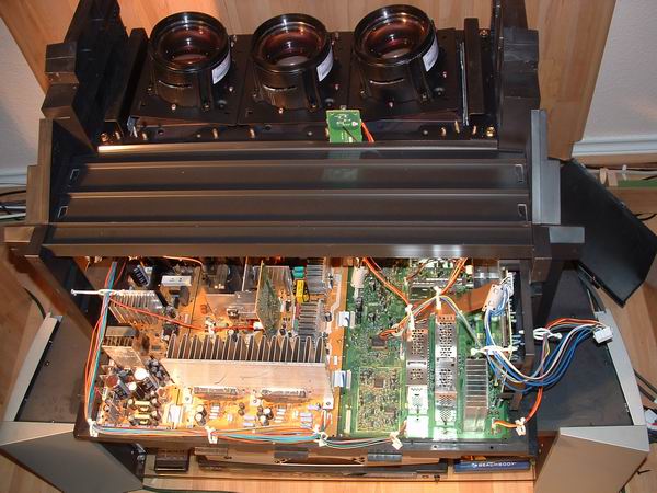 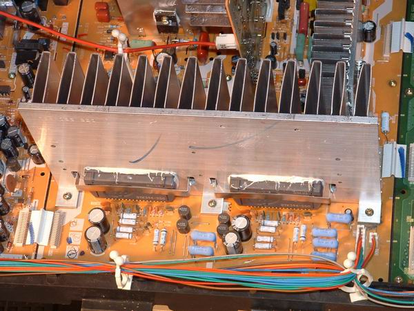 |
|
|
New member Username: OlliehdtvPost Number: 1 Registered: Jan-07 | Well, I finally decided to swallow my pride, and muster up some humility to post. My story is not as pretty as most that I have read here on this message board. My TV had been down for about 3 months. I worked on it when time was available, using the guidance of this board. I had contacted Steve a couple of times, he offered great advice. (THX STEVE). Anyway, I got tired of messing with it, and took it to a pro to work on. Removing the Lite Box saved me 100 dollar pick up and delivery fee. So, the service center told me that, the convergence IC's I had soldered in were fine. They told me that the RED tube had blown out, and Mitsu does not have these parts available anymore, and even if it was available, you couldn't just replace the RED tube, you'd have to replace the blue and green at the same time, due to phosphor burn in. So long story short, my TV is pretty much worthless. So here's my thought. Either, I get a whole lite box from someone that has had something go wrong with there screen (scratched or cracked) or chassis. Or there is nothing wrong with my chassis or screen, sell that to someone who needs it. I'd prefer to just buy a used lite box, my convergence board is good, so if you could guarantee me that your "guns" or tubes are good, I'd buy the Lite box from you. What we need is a MISTU TV parts junk yard. LOL.... Anyway, I realize I'm grasping for straws, but I love this TV, and really don't have the funds to purchase a new one. I have a 65" WS65857 Any suggestions would be great. THX. Ollie |
|
|
New member Username: DmgceoPost Number: 1 Registered: Feb-07 | I'm about to try and replace the two convergence STK392-570 IC's with new ones. From those who have posted here, I think I understand the removal process - but - do I solder the new IC's in their sockets FIRST then put the heat sink back on and screw it down or put the IC's and heat sink back on then solder the IC contacts ???? help!!! | |
|
New member Username: AdpantherSan Jose, CA Post Number: 2 Registered: Jan-07 | Well I just finished with mine today. My Tv is a little different I had one 27pin STK IC STK393-110 Steve helped me with the part number. Anyhow I had no experience soldering so I had to spend about $60 for equipment (MCMINONE.COM) and $20 for the IC (ELECTRONIX.COM) I took apart some old electronics that I had around so I could get used to soldering on pcb. Spent about two or three hours getting used to desoldering and soldering. O yeah and 14.50 for the manual (USER-MANUALS.COM) <------ This was a very high quality pdf BTW I removed back cover removed three pieces of wood 1 rear and 2 1 on either side of light box. Removed speaker cover and panel. Disconnected three connectors from front of tv. I removed 3 screws from light housing. Removed Entire Light Box. tried to tip back but center CRT PCB would not allow it. Had to disconnect all wire ties release chassis, slide out and tip up chassis to access bottom. The plastic chassis allowed barely enough room to access pins. I tried to use a desoldering pump but with the pins so close together I could only effectively desolder 3-4 pins. So I went to a #1 Braid. After a while of frustration desoldering while lying on my back the old IC was free. I tipped Chassis back down and removed cover over IC mounted to Heatsink ( most of your tvs don't have this I understand.) I used a knife and cut through the heat sink paste and removed the IC. I cleaned all surfaces of both sides PCB, heatsink and new IC with Alcohol. I had to remove the heat sink to insert the pins but found it helpful to remount the heatsink with paste becuase it held the IC in place. { Tipped it back up and soldered it in. Reassembled everything. Took about 4 hours not counting practice time. I cleaned the lamps while I had it out and it looks better than it did when I bought it. I had to reset defualt convergence when I turned the tv on Scared me both red and blue were off before I did this. I also have a small dirt or debris particle on the back of the lenticular I have to clean off in the next few days. Thanks for all the posts everyone I would not have paid someone to fix this and it would have broken my heart to throw it away I wish I would have had more experience and a helper would have been handy. Plus accidentally melting plastic on the chassis 8 inches from your face doesn't smell good. Dave |
|
|
New member Username: Dmcd327Post Number: 1 Registered: Feb-07 | Hello, I'm a new member and figured I better continue on this thread then start a new one. Here's my problem. I have a vs-45609, I have the same hourglass effect or 3-d effect. RED around the edges. I have read many forums (this being the best),and have tried to repair myself. First let me say I'm a rookie when it comes to electronics, but I can find my way around. Second the IC convergence STK393-110, I only see 1 and I read alot of 2 in other tv's. Am I correct? Also I read of a center pcb, I only have 2 pcb's and the convergence ic seems to be on the left next to the large heatsink looking from the back of the tv. My symptoms seem to be a little different. Yes I have the hour glass, red ghosting but if I let it warm up for a couple hours it goes away and stays away. While warming up I can take a piece of wood, wiggle the heatsink and it will fix it for about 1 to 20 minutes. I'll try pushing on the heatsink again and nothing. Then I'll wiggle some wires and it will fix for a little bit again. Then sometimes none of these do anything. After its all warmed itseems to correct itself. I can actually watch the red being pulled into alignment and you can see it struggling. After its fixed itself if I turn the set off and immediately on, no change, still fixed. If I turn off for about a minute and then back on fixes itself in 1 to 2 minutes. While fix I'll wiggle some wires, push on the heatsink and nothing. Cannot duplicate the ghosting. Now I did pull out the boards, left them attatched to the plastic tray, turned upside down and set it on an open cardboard box so no pressure was allowed on the circuitry. I then resoldered STK393-110. I did not remove the old solder, just remelted and added a little extra. Was this a bad idea? Should I have removed the old solder? Did this twice as both times did not help. Will a bad chip produce thse results? Should I order 1 and replace it? One last thing, connected to my heatsink is another chip, much smaller and has 1kdj printed on it and has about 6 pins. Anyone know what this is? |
|
|
Bronze Member Username: SkslvnvPost Number: 37 Registered: Mar-06 | Darrell, The post just previous to yours should have answered most of your questions. Yes, you only have one convergence amp IC and yes, you should just replace it. If you need a more complete explanation as to why, please read back though my posts for the answers. The layout of the chassis' may vary, but the circumstances are the same. What is true for the two IC models is pretty much the same for the single IC models as well. Steve |
|
|
New member Username: Dmcd327Post Number: 2 Registered: Feb-07 | Thank you SKSLVNV for your advice! Replaced IC and picture is great. It did take me 2 times though. Must have not soldered a joint correctly the first time. But I do have a new problem that was not there before. When the tv comes on I have a light buzz through the speakers. It does not increase when I turn the volume up, but it does go away with volume all the way down or mute.Any ideas? I checked all my joints around the IC area making sure I didn't melt any. All looked good. Thank you. | |
|
New member Username: Dmcd327Post Number: 3 Registered: Feb-07 | Hey everyone, I'm a little worried now. I turned on my tv the other day and the convergence was messed up again. Lasted about 10 sec, fixed itself for about 20 sec, messed up again for about 10 more sec, then was fine the rest of the day, and thats powering off on on multiple times throught the day. Yesterday on first power up it was messed up for about 10 sec then fine again all day. Today a repeat of the other day. When I replaced the IC did I not get a 100% connection? Could it be a faulty part? I got it from Electronix. Could it be something else? Also noticed when the picture is good I have 2 little yellow splotches towards the top of the screen. Is that a cleaning issue? Please Help. Thanks |
Main Forums
Today's Posts- Home Audio Forum
- Home Video Forum
- Home Theater Forum
- Car Audio Forum
- Accessories Forum
- All Forum Topics