Archive through October 15, 2006
|
New member Username: NogeniusPost Number: 4 Registered: Jul-06 | andy, congratulations on your success! i will be checking my thru hole connectors this weekend. thanks for the tip. |
|
New member Username: VolverinePost Number: 1 Registered: Aug-06 | Where can I buy original Mitsubishi IC STK392-570? |
|
New member Username: Andy57sJackson, New Jersey USA Post Number: 4 Registered: Jul-06 | |
|
New member Username: ScreamerPost Number: 2 Registered: Jun-06 | I had a Mits WT-46805 bought in 2000(1999 model) and it failed in 2006 (low actual hour usage). The CRT's coolant had dripped onto a board and caused the picture to fade out(still had sound). The service tech said they were'nt worth replacing (1200-1500 us). He also said this was'nt the only set he's seen this happen to (Mits common problem). He cleaned up the inside and put a plastic shield to protect the board(temp solution). The set worked but the convergence was off along the edges and could'nt be fully corrected,it also started to bow-tie. I had a 5yr warrenty and it failed 12mo out of warrenty. After a round about with Mits,they kicked back some cash toward another tv (a possible fire hazard?). |
|
New member Username: VolverinePost Number: 2 Registered: Aug-06 | I couldn't find STK392-570 on mitsubishi site. So I ordered them from electronix.com BTW How do I remove these connectors between PCBs? They seem to be hard to move. From which side do I remove them? Deep groove side or flat side? Also, how do I put them back in these tiny slots? Any tricks? Techniques? |
|
New member Username: Swin_manPost Number: 3 Registered: Jul-06 | volverine, The white connectors come apart from the side of the connector that you can feel a little bit of a hang over on both sides of your fingers. They come apart very easy I did it with my fingers. Just push them back into slots making sure that they are aligned with the other side. I also ordered my STK392-570 from electronix.com but for some reason my green lite will come on my tv when I turn it on and it will turn off in 3 seconds. I have not figured that one out yet but I will have to get back into it before winter. Hope you have better luck than I did. |
|
New member Username: Andy57sJackson, New Jersey USA Post Number: 5 Registered: Jul-06 | Where can I buy original Mitsubishi IC STK392-570? Mitsubishi Parts Department: 1-800-553-7278 |
|
New member Username: Andy57sJackson, New Jersey USA Post Number: 6 Registered: Jul-06 | On my VS-45609 I found it a lot safer to leave the 2 PCB's connected with small white connectors in the plastic chassis. I just removed the smaller connectors with wires from the 2 circuit boards, Released the chassis locks, pulled out the Circuit Board chassis (Didn't remove the Large Power Supply connector or the White wire to the HV Transformer, they had long extra wire so I could flip the circuit boards over to solder them. Also, It is easiest to remove the Heat sink and cut the pins off at the STK Body, then heat the single pins and pull them from the board. Went back later with unsoldering braid to suck all the old solder off. |
|
New member Username: VolverinePost Number: 3 Registered: Aug-06 | Finally I received my ICs on friday and here is the update on what I did. 1. I opened up the back cover. Then took out black plastic cover on top of all input/output connectors. 2. Took out front speaker grill and another panel. I kept a note of location of screws. 3. In order to remove middle PCB, I had to - -- remove three screws (from back side of TV) -- remove two screws (from front side of TV) These screws hold the PCB down on plastic tray. 4. I had a question about those white connectors which connect to other PCBs. There are three on one side and two on other. I used a big flat head screwdriver to remove them. They remove from side where you see shiny flat wires not from grooves with wires in it. I put the head of screwdriver in an angle at the side of jumper, resting one side on PCB and twisted it slowly and it popped open. 5. Now heat sink screws. They can be explained simply as "pain in @ss". The ICs are sandwiched between heatsink and another piece of metal. They are held together by three screws. I removed them first and then removed the metal strip. Then removed the three screws from heatsink which hold heatsink and PCB together. Without removing these screws the PCB won't move. 6. There are 5 connectors on front and 1 connector on back. I removed them making note of which one goes where. 7. Finally I removed PCB from TV. Removed ICs and replaced them with new ones. Then used new heat transfer paste and put everything back together and TV doesn't have convergence problem anymore. Times when I said "S***!!" ========================== 1. While removing both ICs, I use desoldering gun to remove most of the solder. But as mentioned in previous posts, the PCB copper layout is very fragile. You will defintely remove the copper layout. One IC removal damaged copper layout of 4 pins. For removing other IC, I followed one of the advises to cut off the pins. This is definitely recommended process unless you have some high-tech temparature maintained soldering gun. While removing first IC, I used a tool which accidently scratched across back side of PCB but fortunately it wasn't deep and nothing was damaged. I should have been more careful about it. Before mounting ICs, I used a razor to expose more copper around damaged pins. After mounting ICs, I bent the pins so that the pins touch exposed copper. I maintained alternate pin soldering between ICs and mounted both of them. (If it would not have worked, I was thinking to buy teflon wires and connect them directly from pin to next component.) This PCB doesn't look like multi-layered so they could have made it more robust. 2. After mounting heat sink, front connectors, metal strip on heat sink, connector in back, three jumpers to one side of PCB, I figured out one of the jumpers on other side is under middle PCB. There is no way to get it out unless you remove entire assembly. I had to remove everything again just to get this jumper from underside of PCB. 3. While putting PCB connectors, I noticed that one of the wire popped out. I used small screwdriver to push it back in. Info: ===== Model: WS-55809 Problem: Convergence IC: STK392-570 Source: electronix.com Tools: All sorts of screwdrivers (Small ones especially useful), soldering gun, desoldering gun, flux, pliers ... Paid: $28 (2 ICs, heat transfer paste + Shipping) Time taken: 9pm - 4am (7 hours!!!) That's all. Finally Cartoon Network can be watched again !!! |
|
New member Username: GavincurtisPost Number: 1 Registered: Aug-06 | My 65907 just began the bowtie effect too! Resoldered the very same two STK392-570 hybrid IC's and like new again. I am also aware of these hybrid modules failing because they operate at high temperatures and need more cooling. As indicated by at least one other poster here; as well as my own experience fixing MANY of the Technics Class-A home theater amplifiers using similar hybrid IC's in the early 90's. The only way to keep the amplifier from failing again was to install a computer grade fan that runs all the time. Afterwards, the device operates very cool to the touch and solved the problem permanently. The friends whom I did this repair still have their amplifiers to this day. So I installed a 4" 12V computer fan onto the heatsink and tapped off the TV's switched 5 volt logic rail to power it. Fan runs at a low and quiet RPM, but cools down the heatsink vastly. Hope this keeps the STA392-570's in a happy state of zen; allowing that expensive TV to be around for a very long time. When convergence is dead on... this TV still has a better picture in my opinion than many of the DLP and LCD TV's I have seen so far. |
|
New member Username: GavincurtisPost Number: 2 Registered: Aug-06 | You can also purchase the STK392-570 on ebay for about 10 dollars each from multiple sources. It's a no brainer to replace both or at least keep a second set on hand at that price. The originals will ultimately fail in the useable lifetime of the TV; with the existing heatsink cooling capacity. I figured they would be much more expensive! |
|
New member Username: Mitsubishi65inchPost Number: 1 Registered: Aug-06 | I have a Mitsubishi WS-65908 Diamond Series 65" inch tv, and I'm having the same problem. I live in Las Vegas, and I called a few repair stores that were listed on Mitsubishi's website. Over the phone I explained the problem and was told it would cost between $300 and $400 to fix it ($200 minimum charge just for labor). I was offered a whopping $100 by one of these repair stores to take the tv off my hands. I will be moving across the country by the end of September, and I want to get rid of the tv since it will cost quite a lot to move it. I'd like to get more than $100 out of it. Does anyone out there have any ideas? Should I fix it and then try to sell it by the end of September, or should I just take the $100? |
|
New member Username: Mitsubishi65inchPost Number: 2 Registered: Aug-06 | Also, if I have the tv repaired, will it once again have this same problem a few years from now anyway? |
|
New member Username: SkslvnvPost Number: 4 Registered: Mar-06 | Brian, I sent you a private message. If you don't get it, use the board to send me a private message and I will respond. |
|
New member Username: GavincurtisPost Number: 4 Registered: Aug-06 | It's an easy fix to bring the set back to life again. about 1-2 hours total time and the parts were only $20.00. Overall, the electronics are very well made in my opinion. The power supply/CRT driver/convergence and audio PCB's (2) are unfortunately single sided circuit boards vs multiple layer. High temperatures of certain components will cause solder fatigue over time. But all connections looked great except for the convergence driver IC's; which indicates the mechanical stresses from high temperature operation. I installed a fan and everything operates much cooler now. Convergence driver heatsink is mildly warm vs too hot to touch as before. The existing driver chips were still okay, just bad solder connections from thermal expansion/contraction of the device's leads. But I replaced them anyways because of the low parts cost (20 dollars for both) and will keep the originals as a backup just in case. I don't know why these TV's are being considered junk already. They have a great picture. They are more bulky than plasma. But plasma phosphors fade considerably in 2-3 years time of use. LCD's are grainy.... I am still waiting for the visual promises of DLP before I'll replace my 3 CRT projection TV. SKSLVNV thanks for the schematic files. They downloaded in about 12 seconds via cable internet. I'll definitely reimburse you. |
|
New member Username: GavincurtisPost Number: 5 Registered: Aug-06 | Brian, If you solder the new convergence driver IC's into place with a lead free silver solder and do the same for all bulky/mechanically stressed components (including connectors).... TV should remain trouble free much longer than another 5 years. |
|
New member Username: PtpinkerNew Hampshire USA Post Number: 1 Registered: Aug-06 | Hi all, Great post...I'm about to try the IC replacement on a WT-46809 this weekend. Any brave soul want to give me some soldering tips. I've done some small soldering projects before, but I'm a little nervous about permanently damaging the set... Also, any additional details/photos on what to tap into for power on the 12V DC heatsink fan? Thanks! |
|
New member Username: MickeynguyenTallahassee, FL USA Post Number: 3 Registered: Jul-06 | It's not so bad, if you have done any kind of soldering & de-soldering before you will be fine. Just be patient during the de-soldering with the solder wick and make sure all the solder is removed from the IC's pins before pulling out the IC. Since this is a single layer board, the traces and via hole won't like the abuse. After remove most of the solder, I use the soldering iron to move the pin to the center of the hole. You can wiggle the IC before remove them just don't use too much force if it doesn't come check to see which pins still have solder. One other thing, don't use too much of the heat-sink paste, this is the case where more is not better, a thin uniform thickness film on the back of the IC will do the job. A little of this paste will be squeeze out around the edge when you tighten it back down is perfect. Sorry I don't know the location of the 12Vdc heat sink fan. Good luck! |
|
New member Username: GavincurtisPost Number: 6 Registered: Aug-06 | You can also use a pair of precision wire cutters to clip each lead from the old IC's. Then melt the solder and remove each remaining IC lead with needlenose pliers the instant the solder flows. Do for all remaining pins. Once all the pins are removed, use desoldering braid to remove the remaining solder from the pads. Work on one pad at a time and work as quick as possible. The less time the iron is on the pad, the less likely it will be damaged. This method works great to prevent damage or lifting of the pads for first time solderers. Even if a pad were to lift, you can always use jumper wires to fix a mistake. Also be sure to resolder each set of the three green power resistors next to the IC. I found that the resistor's solder connections were losing integrity as well. Regarding the 12 volt fan I installed, the TV didn't like it. It would sometimes not respond to the remote, no idea why but removing the fan brought the TV back to normal. So I went with a 120 VAC fan instead. I ended up using a Radio Shack 273-0241 4" 120VAC fan (excellent quality and quiet) and a 275-233 12V reed relay. On that same power board with the 2 IC's you are replacing is a 12V main power relay for the TV. I installed the reed relay so that its 12V coil is parallel with the TV's 12V relay coil. The reed relay only draws 11 mA so no problem for the TV's relay driver electronics. Then I used the reed relay's contacts to switch the fan on or off. I would be happy to email a diagram showing how to install the relay. It is very simple to do and will not harm the TV at all. I installed the fan to the bottom center of the back panel with the air blowing inwards over the switching power supply components and then directly on the convergence driver heatsink. |
|
New member Username: Andy57sJackson, New Jersey USA Post Number: 7 Registered: Jul-06 | I also suggest re-soldering ALL components that have thru-hole pins going through the board, especially connectors. I found that over 70% of the ones in my TV were fractured, you could see the fracture ring on close examination. It will save you aggravation trying to trace down intermittent problems caused by the solder joints changing resistance due to expanding/contracting. |
|
New member Username: PtpinkerNew Hampshire USA Post Number: 2 Registered: Aug-06 | Thanks for all of your help and suggestions. I'll let you know how it turns out next week. GavinCurtis - I sent you an email message. Thanks again |
|
New member Username: HaupfearSimpsonville, SC US Post Number: 1 Registered: Aug-06 | Thanks for the help guys! My dad received the 55" version for free with the hourglass effect and I repaired today. Took a few pics that might help. The first one is STK392-570 and heatsink assembly and the second one is the high voltage necks and red wiring to avoid (even unplugged). Thanks again! btw - I had good solder joints and just cleaned the heastink and chips with rubbing alcohol and then reapplied heatsink compound (from Radio Shack - $2). So far so good... http://img.villagephotos.com/p/2002-12/74415/STK392-570.jpg http://img.villagephotos.com/p/2002-12/74415/high_voltage.jpg |
|
New member Username: FailedrepairPost Number: 1 Registered: Aug-06 | Boy did I screw up! I have a Mitsubishi WS55809 and from reading everything here, I knew the problem was with the STK392-570 so I ordered two of them last week. Today I started the repair.... I had no trouble pulling the main board out. I cut the old STK392-570 semiconductors out and cleared the solder. I installed the first STK392-570 without any problems. I started to solder the other STK392-570 and found one of the eyelets (I think that's what it's called) was missing. I looked everywhere and couldn't find it. It's impossible to solder now. But I made another serious mistake. I have a desoldering bulb and used that to clear out the old solder. This however didn't clear quite enough out of the holes for the new STK392-570. So stupid me used a .8mm drill bit to clear them. That's probably what caused the eyelet to disappear. I used this on all the holes so most likely I have damaged all the holes. I've never worked with a PCB before and didn't realize how these are constructed. Is my main board now trash? Did I just throw away my TV? Call me stupid, that's OK (my wife is). |
|
New member Username: MickeynguyenTallahassee, FL USA Post Number: 4 Registered: Jul-06 | Tony F, You still may be able to 'save' the board. This board is single side board so there is no copper/plating in the holes that you drilled. Hopefully, you only ripped out one or two of the 'eyelets' (actually they are called pads). Look at the bottom of the board where you are missing the pads, there should be a copper trace that was connected to the eyelet. You can solder the IC pin directly to the trace by bending the pin toward the trace if it can reach it. You may need to scrape the trace to expose some copper. You may also use a small wire (lead cut off a resistor, capactior, etc)and solder it between the pin and the trace. Don't throw the TV away just yet. My wife call me stupid, too and I design circuit board for a living but can't go anywhere with more than two turns...I would get lost. All of us mess up at one time or another. E-mail me mickeynguyen@yahoo.com if you can't get it fix (but you will) and I give you my address so you can send me the board & I repair it for you (no charge, promise) and get it back to you. |
|
New member Username: FailedrepairPost Number: 2 Registered: Aug-06 | Mickey! You are one nice guy. I'm happy to hear I won't have to buy another TV. I hardly ever watch this one as it is, but when I do, I want to at least get the best picture I can "for the money" and that's why I bought this in the first place. I can't see any of these copper trace's you talk about so obviously they are hidden there somewhere. I have one of those jewler's magnifying goggles with lights and I can't see these copper traces. When I cut off the old STK392-570's (close to the IC) I have all those wire stems I could use and I also have all kinds of small wires anyway. I've attached a pic, but not sure if you can see what I see. This is the only one I can see that is missing the pad. I've scraped around a little (trying to be careful not to cause more damage), but all I see is brown board. I'll play around with this, but if I can't find a way to fix it myself, I'll email you for an address. 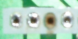 |
|
New member Username: GavincurtisPost Number: 7 Registered: Aug-06 | Mickey, You did not destroy the board. But you will have to run a jumper wire if indeed the pad was connected to another part of the circuitry. If you examine the location where the pad used to be... there may be a lighter green "track" on the circuit board that connected to it. In reality, that "track" is a foil thin layer of copper made metallic green by the translucent green laquer paint applied to the bottom of the entire board. Just follow that "track", (correctly termed a trace) back to the nearest point where it becomes a solder eyelet for the next component. Simply solder a jumper wire to the protruding STK lead with the missing pad. Then solder the other wire end to the nearest component the foil trace goes to. You are essentially bypassing the trace with a wire. The wire is actually much more reliable (not as pretty) than the original copper trace. If you can't fix it, send the board to me and I will be glad to restore it for you. But you should be able to do it very easily. Also, chances are that the pad lifted away because it is a blank... that is it goes to nothing! If no foil trace is leading up to that missing pad, then it is an unused pin so NO PROBLEM!  Many IC's have 20 percent or so of their pins internally connected to nothing. In fact, looking at your photo... it does appear to be no connection pad. Your TV is still alive. |
|
New member Username: GavincurtisPost Number: 8 Registered: Aug-06 | Oops... got names mixed up! Sorry about that Mickey.. that was for Tony. Also didn't realize your offer to help repair Tony's board if he sent it to you. Didn't mean to barge in and step on others shoes. Tony, like Mickey said; that circuit board is a single layer board. So all the foil traces are on the bottom only. There are no hidden traces on this particular circuit board. So if no trace is visible leading up to the missing pad, then that pad was not important. It was only there to provide a small amount of mechanical support for the IC; by merely attaching an unused pin to the circuit board. |
|
New member Username: MickeynguyenTallahassee, FL USA Post Number: 5 Registered: Jul-06 | No problem Gavin...See, Tony there are still plenty of good folks left out here. Gavin is right on about most of the pins may not have any electrical connection so your board is fine. I'll e-mail you my address if you still want to send the board to me. We'll get this thing back up and running in no time. |
|
New member Username: FailedrepairPost Number: 3 Registered: Aug-06 | I'm finally figuring out what you two are talking about. The dark green area is just the board while the lighter green areas are the circuits. It seems this particular one is not connected to anything. I have a schematic of the board (attached) so maybe one of you can confirm this is the case. The pin that I'm talking about is the #3 pin from the left 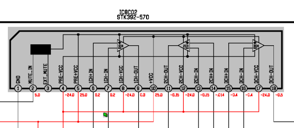 |
|
New member Username: MickeynguyenTallahassee, FL USA Post Number: 6 Registered: Jul-06 | You luck out Tony. It does not connected to any thing so you don't have to do any thing to this pin. Let's us know how it goes....You would need to change your user name, though. Good luck! |
|
New member Username: FailedrepairPost Number: 4 Registered: Aug-06 | I am very glad to hear this. I soldered in the new IC and will begin to install the board after lunch. One thing that caught my attention is that Mitsubishi has only attached these IC's via the heat transfer paste (heatsink paste) even though there are holes for screws in the IC. This is probably why so many of these Mitsubishi TVs are having problems with this. I have marked for holes in the aluminum heatsink so that I can use self-tapping screws and tighten these ICs to the heatsink. I will also of course add new paste to the surfaces before clamping things down. All other ICs are screwed to their corresponding heatsink. I wonder why they didn't do this with these considering that these puppies get super hot. The craftsmanship on this is pretty poor from what I can see. These TVs were also assembled in Mexico (says made in Mexico). Quality control was obviously overlooked. I'll let you know how things turn out and thanks to you both for lending me a hand with this. Isn't the Interent a fantastic place? Tony |
|
New member Username: MickeynguyenTallahassee, FL USA Post Number: 7 Registered: Jul-06 | On my model 65809, there is a metal bar accross the two ICs that clamp both ICs down to the heat sink. Your model may be different, but it definetly poor design on Mits's part for not adequately dissipate the heat, though. Good luck, man |
|
New member Username: FailedrepairPost Number: 5 Registered: Aug-06 | Hey Mickey & Gavin! I soldered everything up, installed the main board and double checked all my connections. Plugged it in without any incoming signal. I turned it on and PERFECT!!!!! Everything seemed to work exacty as it should. So again double checked all connections, put the back panel back on and plugged in the SAT. Turned it on again and what a wonderful picture!!! Finally HD without the convergence problem. I haven't even gone through the setup to optimize anything yet and the picture is absolutely beautiful. If it wasn't for you two guys I might have had Goodwill over this afternoon to pick this up, but instead I'm going to watch football this weekend in HD! It's been almost a year since the convergence problem first started. Usually I would wait or turn off and then on again and the picture would return to normal. But for the last several months I would turn it on and might not be able to watch TV for the entire night. It was driving me nuts. Now I turn it on and there it is. A perfect picture. Mickey, I think I might get some tonight! My wife is back to thinking I can do anything. So not only have you two saved my TV, but also my marriage (just kidding. My marriage isn't in that bad of shape). Thanks again you guys. You've really been a great help. I also want to thank this site for being here so that we can do all this. This is what the Internet was initially created for. The exchange of information. Oh yeah, if anyone needs a service manual and/or a schematic in PDF format which covers these models: WT-46809 WS-55809 WS-65809 WS-55819 WS-65819 Just let me know and I'll zip it up (about 5MB) and send it to you. Tony |
|
New member Username: MickeynguyenTallahassee, FL USA Post Number: 8 Registered: Jul-06 | Alright TONY...you are the man. You are very welcome, Tony. You got to love the internet for these, big corporate can't hide their quality problems any more. Root for my Cowboys (I don't know why I think they are mine) when they are not playing against your team, man. Being married is a good thing, you are always challenged and learning new way to be patience. |
|
New member Username: FailedrepairChandler, AZ USA Post Number: 6 Registered: Aug-06 | Hey Mickey, You bet I'll root for the Cowboys. Why not? The AZ Cardinals suck. I shouldn't say they suck because who knows what this season brings? |
|
New member Username: GavincurtisPost Number: 9 Registered: Aug-06 | The truth is out there... hehe Just got to search for it. Internet is one of the most powerful solutions for DIY. Keep learning.. because you will soon could be engineering circuit boards that won't fail like this one did. |
|
New member Username: MotleyscrewBakersfield, Ca USA Post Number: 1 Registered: Sep-06 | Howdy guys & gals, Im new to this board, and would consider myself comnpletely ovlivious on how to do the procedures above. My Mtsubishi WT-5609 has also decided display the picture in the hourglass / fisheye junk. I wouold like to provide the parts to the business that is fixing it, since I can probably get a better rate that way. Could one of you confirm that this is the part (s) I need? http://cgi.ebay.com/ws/eBayISAPI.dll?ViewItem%26item%3D200022812107 And if it is the correct part, do I need three of these or just one? Do I need anything else to supply to the repair shop? Thanks in advance. |
|
New member Username: MickeynguyenTallahassee, FL USA Post Number: 9 Registered: Jul-06 | It look like the ebay listing link is pulled (scam?). Check your TV model number it usually WS xxxxx not WT. |
|
New member Username: MotleyscrewBakersfield, Ca USA Post Number: 2 Registered: Sep-06 | I messed up on the above post.. my T.V. is a WT-46809. So am I understanding that I need STK392-570 to fix the fish eye? If so, how many do I need? I read somewhere that if I replace the chips with anything other then authentic Mitsu parts that I will have problems in the future. Is this accurate? I will only be buying the parts for somebody else to replace (I don't have the balls or knowledge to do it myself). Just hoping to save some $$ by buying the parts first. Are there any other parts I may need? And finally, If I provide the above parts, what would be a reasonable cost to have them installed & once again make my picture as new. Thanks much! |
|
New member Username: MotleyscrewBakersfield, Ca USA Post Number: 3 Registered: Sep-06 | Heya Micky.. the link still works for me. NEW STK392-570 SANYO IC STK392570 http://cgi.ebay.com/NEW-STK392-570-SANYO-IC-STK392570_W0QQitemZ200022812107QQihZ 010QQcategoryZ4663QQssPageNameZWDVWQQrdZ1QQcmdZViewItem I just need to make sure that these chips listed above (STK-392-570) will work just as well as factory chips. How many do I need? 3? And If I bought them, how much should I expect to pay for installation. |
|
New member Username: MotleyscrewBakersfield, Ca USA Post Number: 4 Registered: Sep-06 | Here is a link to the monitor itself. The problem I have is that I am on disability now, and need to do whatever I can to cut costs (like buying my own parts to be installed.) Even though I can't install them myself, I'm sure SOMEBODY will install them without ripping me off??? It is absolutely maddening to try to play a vid game, watch news, or watch any other program for that matter when the center top and center bottom are seemingly being sucked into a black hole in the middle of the screen, and the red green & blue don't match up on the top, bottom or sides. |
|
New member Username: MickeynguyenTallahassee, FL USA Post Number: 10 Registered: Jul-06 | Hi Mike, I bought the IC'c from this seller for my repair. They work great for me. You will need two of these chips. The installation including remove/replace the board from the TV then replace the IC should not taken more than an hour for a 'professional'. My guess for the installation would be less than $150. |
|
New member Username: WoofiepoohPost Number: 1 Registered: Sep-06 | Well I installed the chip set and I have worked on PCB before and did a gret job of replacing. I turned on the tv and just the green light came on and after 2 sec. it turned off. Well now what? So I replaced the old chips to see if the tv will turn on but the same thing happened. Why me ? I'm getting another set of chips but I know something went wrong with the board. Any help out there? How I would love to buy a board and just put it in but I have looked all over and no luck. So I must repair the one I have. Anyone have a old board ? or know know fuse I should change? Thanks Neil sales@gionetart.com |
|
New member Username: WoofiepoohPost Number: 2 Registered: Sep-06 | Still wooking on the Board. Finding that fuse F9A05 (5 amp )was blown. I replaced with a makeshift one and that one went bad too. Okay now what! |
|
Bronze Member Username: PlaneracerPost Number: 11 Registered: Mar-06 | Neil Rudofsky , Check the ic's pins for short if ok check other fuses on board. (+26 and -26v lines.) Check the resistors arround ics. (if some of them bad they colors will change from overheating) if all ok, then replace fuses and unpulag converg. connectors from r,g,b yokes. if tv stays on then 1 of yokes bad. is not, pulled a converg. generator from board and try. if tv will stay on then bad generator good luck |
|
New member Username: WoofiepoohPost Number: 3 Registered: Sep-06 | Gave it a try but no luck. Board looks great. The one thing that did happen was when I pluged in the TV nice AC ark to the plug. Checked fuse still good untill turning on the set then only 1 to 2 sec geen light off...Neil |
|
Bronze Member Username: PlaneracerPost Number: 12 Registered: Mar-06 | Neil Rudofsky , pull ics from board. replace fuses and turned on let me know what happend |
|
New member Username: WoofiepoohPost Number: 4 Registered: Sep-06 | All was working great until I got the hour glass that came and went. All I did was change the chip set..Then this. Iknow how to solder and remove parts. My work was as good as gets. I did QC work on PCB. and check for any damage on the board " Nothen" but dust...Neil |
|
New member Username: FailedrepairChandler, AZ USA Post Number: 8 Registered: Aug-06 | Just wondering.... Once you have these new convergence chips installed (WS-55809), the next step I felt appropriate would be to optimize your convergence settings. Let's face it, the initial settings have a lot to desire. A friend of mine paid a guy some huge bucks to come in and optimize everything and he said the majority of time was spent with the convergence settings via the service menu. I wrote down all settings prior to making any adjustments so I have all the original values at hand. This leads me to my next question. Obviously you start with the geometry and green (from what I understand). But what I notice about these initial settings is that the distances between the green blocks are different (64 block convergence menu). Tilt, skew and everything else seems fine. But the lines are a little wavy both horizontally and vertically making me believe this was a quick setup at the factory. These lines can be adjusted easily using the remote, but where would you begin? Do you make all green box openings equal in size? Do you use a straight edge of some sort to try and straighten your lines? Since you can move all lines either vertically or horizontally, there must be some way to begin the process. If you leave it at factory defaults I would think you'll never have a perfect picture. I'm just wanting to learn what the pros do so that I can try and mimic the process without spending a small fortune. There must be some kind of guidelines these guys use. I've already read about using binoculars during the convergence process (the only way to go). I also have the Avia DVD. Thanks for any suggestions. |
|
New member Username: WoofiepoohPost Number: 5 Registered: Sep-06 | Thanks Tony But to get to that point I need to get the TV to turn ON.. It keep blowing the Fuse! I need big time help now..I'm thinking now about buying another TV and just give up. I hate be a looser too.. Neil There has to be someone out their who knows what going on... |
|
Bronze Member Username: PlaneracerPost Number: 13 Registered: Mar-06 | Neil, Like i said pull out ics , replace blown fuses. See if turns on. if not you have some other problem. not converg. Then, you have to check somethink else. try that. |
|
Bronze Member Username: PlaneracerPost Number: 14 Registered: Mar-06 | Tony F that is easy, takes a 15-20 min to adjust a SD and HD modes go into service mode. you have to be ready to use a video, audio, enter and arrow keys press button #4 and chouse a color with a audio button. you need to start with green color only because when you move a green other colors moves to. start with green, try to make all boxes same size., then with auduio button change a color and adjust next color. button #5 om remote will take you back to geometry screen. on here you can change skew, h,v lineraty, size and .... if you liked all adjustments press menu to exit. to adjust a hd mode you need a hd signal connected to dtv input. then chose a dtv input and enter into service menu. is some other way to doit. you have to go into menu **70 then change dtv port from auto to 1080i with enter button and exit with menu button. in that way you dont need a hd generator or so then enter to menu **59 and adjust a converg. at end you have to go back to **70 screen and change 1080i back to auto. that it good luck |
|
New member Username: FailedrepairChandler, AZ USA Post Number: 9 Registered: Aug-06 | Thanks t. I've already used the service menu to work with convergence options so I know how to get around. I've recorded all settings including all the different settings in each block in the fine mode for all colors so if I screw things up I'll know how to get back. The skew, tilt and all other settings in the course menu (green SD/HD) is just fine as far as these settings are concerned. My concern was the size of each box. Mine are way off and even wavy lines (which can't be adjusted via the coarse menu). I've found some boxes are as much as 3/4" different in width and/or height than other boxes. While the overall coarse settings are OK, the fine adjustments obviously are not. So it seems all boxes are to be of the same width and height. I guess it would be easy to create a template out of mylar or something and measure equal distances to create a grid template. Then take this template, place it on the screen and start the fine adjustments to line everything up. I realize SD and HD are different so two templates will be required. Once the intial green is set I can continue with the blue and red fine adjustments. Hopefully this will set the geometry where it needs to be and even make it easier to fine tune. Thanks again for clarifying that all boxes are to be of equal size. |
|
Bronze Member Username: PlaneracerPost Number: 15 Registered: Mar-06 | box sizes on hd and sd will be diff. more boxes on hd. and little harder to adjust on hd. wavy lines? i never seen that on mits. It can be little, on sides or corners. little out of focus or so. some times it is hard to fix that.best way to adjust, just turned converg. over the picture and adjust picture size vert. and horiz. you have to overscan about 1 inch on each side. then start your adjustments. |
|
New member Username: WoofiepoohPost Number: 6 Registered: Sep-06 | Mr T. Pulled chips again and the fuse will blow. I see that the trace from the fuse goes to a transfromer or chock! I don't know what it is I have no paperwork on it. And I have replaced ICS twice so I know it's not them. Fuse F9A05 is not a nice fuse!!! Looks like I have to make up my mind about sending the board to the shop or buying another TV...( Credit card time )..Thanks All for your help..What the best kind of TV now to get DLP - Rear-Pro. - I know no plasma.. I think I shuold start reading good books! They will not brake on ya..Neil |
|
Bronze Member Username: PlaneracerPost Number: 16 Registered: Mar-06 | Neil, Let me look schematics where that fuse go. About new tv. i hate mits dlp. lot of problems. if you think a buying rear projection, then maybe samsung dlp or sony lcd. that just my opinion. |
|
Bronze Member Username: PlaneracerPost Number: 17 Registered: Mar-06 | Neil, What is model number? |
|
Bronze Member Username: PlaneracerPost Number: 18 Registered: Mar-06 | Neli, Fuse F9A05 is -24v line. It runs to converg. ic's . to converg. generatoor. and shotdown circut Q9A53. If after you pulled is tv still shotdowns means you still have short on board. if that fuse blows next step to check a diode d9a61and pull converg. generator from board. Nothink else. -24v only for converg. look at board. check for shorts. |
|
New member Username: NogeniusPost Number: 5 Registered: Jul-06 | Hello friends Could I ask that we go back to basics for a minute? How can I identify a poor connection or one that has failed due to heat? So far I have replaced the IC's on my VS45603, I have double checked my soldering, I have checked for heat (power) at the new IC's, I have checked continuity on the traces, I still have zero convergence control and the f*ing hourglass color separation continues. Does this indicate the Convergence Generator is faulty? Stsklnv says I need a schematic, anybody have one for my model? The set had been stored for a couple of years, I moved it across town and after that it worked PERFECTLY for two days before this stuff started. Any ideas appreciated. Thanks |
|
Bronze Member Username: PlaneracerPost Number: 19 Registered: Mar-06 | carlos, that from mits. site: 1. CHECK CONNECTOR "VD" FOR PROPER CONNECTION BETWEEN THE CONVERGENCE PCB AND CONVERGENCE GENERATOR PCB. 2. SEVERE CONVERGENCE DISTORTION BUT CONVERGENCE WILL ADJUST. THE CONVERGENCE EEPROM DATA MAY BE CORRUPT, DO CONVERGENCE RESET AND REALIGN THE CONVERGENCE. CONVERGENCE RESET CAN BE DONE SEPARATELY FROM E2RESET. (THIS IS NOT IN THE SERVICE MANUAL). ACCESS THE FINE CONVERGENCE MODE BY PRESSING MENU 23594 THEN PRESS 8970 TO RESET GREEN, PRESS THE AUDIO BUTTON TO CHANGE TO RED AND PRESS 8970 AGAIN TO RESET RED, PRESS THE AUDIO BUTTON ONCE MORE TO GO TO BLUE AND PRESS 8970 TO RESET BLUE. Check for bad connections on left far connectors good luck |
|
New member Username: 38superPost Number: 3 Registered: Jan-05 | HI ALL THIS IS A GREAT FOURM SO HOPE I CAN GET SOME HELP I have a Mits WT-46809 that has the hour glass proplem . I would like to replace the board that holds the STK392-570 ICs . I looked at the board and found more then a few bad solder points. Does anyone know where I can get part number for this board or who may have it and what the cost my be Thanks Will |
|
Bronze Member Username: PlaneracerPost Number: 20 Registered: Mar-06 | William F Strosahl , part # for power board is: 930B867003 |
|
Bronze Member Username: PlaneracerPost Number: 21 Registered: Mar-06 | price is about $305.00 |
|
New member Username: 38superPost Number: 4 Registered: Jan-05 | T.. is this a Mits replacement board with all components on it . In other words I just replace, hook up conections and I'm up and running ?? Thanks WILL |
|
New member Username: WoofiepoohPost Number: 7 Registered: Sep-06 | I called Mits. for a new board and OUT OF STOCK. I was told I have to get it rebuit! at a Mits Service Center. But I have the 65". I'm sending it today and going to fix this TV once and for all. I will not lose..THEN I"M SELLING IT!!!! Put what I get for it and pay down the new one. Went to Sears and bought another.( 10% off and no intrest 6 months ) From what I see the big screens don't last more then 6 years..They must be rated in dog years (7 x 6 =42years) So I did the math take what you paid Div.it for as long as you owned it and that what it cast you per year. And the newer TV have a few more upgrades too. Good luck with your repair and hope that nothen else will go wrong. Note: "Keep your TV untill your service contract is over THEN SELL....Neil" |
|
New member Username: NogeniusPost Number: 6 Registered: Jul-06 | Thanks t I have tried the convergence reset, no luck! In any color I can push the adjust button til doomsday and no change. Once again I will check connectors. Far left? Do you mean that my problem is most likely on the left PCB? Should I pull the others too? (jeez, I hope not) |
|
New member Username: SkslvnvPost Number: 5 Registered: Mar-06 | In an effort to bring some sanity to a situation that is quickly getting out of hand, I'm going to try to offer some advice to everyone that is following this board. A few well-meaning, but misguided individuals have been dispensing information here that is simply incorrect. Judging by the constant stream of emails that I receive, many people are in way over their heads. Even though I've said most of this before, I will offer it again in hopes that some people will understand their limits and not ruin their TVs. 1. You NEED to have better than average soldering skills to be able to make these repairs. You simply cannot learn this as you go. You should use a temperature controlled soldering iron. You should be familiar with de-soldering techniques and know how to do all of this without damaging the board. Cutting the leads off of the IC and then unsoldering them one at a time is NOT the correct method of de-soldering. You are adding more stress to the solder pads than necessary and are jeopardizing permanent damage to the board. Even the best techs will damage a trace once in a while, but without the proper tools and experience, you can easily damage every single pad and make a huge mess. The chassis should be pulled far enough out of the cabinet to be able to remove the circuit board completely from the set. I also strongly advise that you label and document every single plug and wire you disconnect and then use that as a guide when you reassemble. 2. In an earlier post, I explained that there is a huge black market on these IC's. Factory rejects and counterfeits are flooding the market. If you choose to buy from a no-name supplier (especially eBay), you will risk putting unreliable or defective parts back into your set. The most expensive parts option is Mitsubishi, but at least you have the assurance that each part has been tested and certified to be within specifications. In 30 years in the service business, I never received a bad part from Mitsubishi. I can't say that about most other parts sources. Less expensive options include companies like MCM electronics, which has been in the parts business for many years. Both of these companies will stand behind their parts (as long as you don't cut the leads off). The old adage that you get what you pay for is very true here. For those who want to learn more about counterfeit components, here is a great link: http://www.designchainassociates.com/counterfeit.html 3. The STK series IC's have been manufactured by Sanyo for over 20 years. They have been used in everything from audio amplifiers to power supplies. As convergence amplifiers, they have been used by every major Japanese manufacturer including Sony, Panasonic, Toshiba and Sharp. The primary cause of failure in all of these applications is heat degradation. It is my experience that no matter what you do, these components will eventually fail from heat. It's just the nature of the beast. As with any amplifier device, proper alignment is essential to having the device operate within the temperature parameters designed by the manufacturer. If you purchase a part that does not meet the manufacturer's specs and then align the set to compensate for the deficiency, the circuit will run hotter than expected and lead to premature failure. Again, I cannot over stress the importance of having good parts to begin with. 4. While adding a cooling fan seems like it might be a good idea, it is really ill-advised. A few manufacturers have used fans through the years, but most have avoided them for one very simple reason, dust. In the early days of rear projection television, the optics were "sealed" inside of a dust proof chamber. This helped to prevent the build-up of dust on the optics. Dust in the projection lenses and on the mirrors can seriously affect picture brightness and quality. Modern designs have gotten rid of all dust proof designs and are very susceptible to the dust contamination. A fan will almost guarantee an air flow inside the cabinet that will deposit dust very quickly on the optics. Fresh heat sink compound works wonders. Despite what has been said, the engineers are smarter than a guy who has fixed one TV. 5. It is the height of irresponsibility to advise someone who is not a technician to go into the service menu and adjust ANYTHING. This is like giving a child a loaded gun and sending him outside to play. There are so many things you can do wrong I don't know where to begin. And it doesn't take much! The worst thing you can do is dump all of the adjustment settings that are stored in memory. Once that is done, you will probably not be able to find anyone who is willing to try and restore all of the data. Service menu codes are readily available in the service literature and if you are able to comprehend their very technical nature, buy a manual and get the info for yourself. 99% of the time, if your soldering is good and your parts are good; you will not need to do any adjustments. If things are really out of adjustment, it is a sign that something is wrong! If you proceed and try to correct an error with adjustments, you will likely never get it back to where it needs to be. I'll share the advice I was given many years ago, if you don't completely understand what it does and how it works, DON'T MESS WITH IT! 6. Service manuals are not step by step troubleshooting guides. They are simply a tool to help those who already know how to troubleshoot do their jobs. If you are not an experienced technician, a service manual is absolutely worthless. Some have attempted to provide a step by step approach. That may work if you are dealing with the exact same model number and symptom. There is no canned approach for every situation. There is enough difference, even among the exact same model numbers, that I would never trust anyone's step by step instructions. 7. I cannot teach you how to troubleshoot. You either already know how to do it or you don't. If you choose to try these repairs and it doesn't work, be prepared to call in an expert and let them resolve it for you. A good electronics technician has worked on this skill for YEARS. A smart person knows their limitations and more importantly, knows when to stop. If you have a good understanding of how to use a volt-ohm meter, you can probably do some basic troubleshooting, but you will need to be able to read a schematic diagram and understand what each component does. 8. I get a lot of inquiries about models and problems other than what this particular forum is dealing with. The information that I have given involves V17 and V18 chassis' only. While there are some similarities between these chassis' and other models, they are all different and will likely be different enough that what is true for one cannot automatically be applied to the other. If you send me an email, PLEASE include the model number so I can give you accurate information. 9. Blown fuses mean that something is wrong. There is no such thing as a "weak" fuse. You can change a blown fuse once, but if it blows again, something is wrong and you need to identify what that "something" is. If the cause of the blown fuse isn't obvious, swallow your pride and call a professional. 10. The final warning has to do with the potential for permanent and un-repairable damage you can cause to your set. Projection televisions are particularly susceptible to CRT phosphor damage. This damage is seen as dark lines in your picture that will not go away. They are usually in the middle of the screen and can run either vertically or horizontally. They are an indication of loss of deflection while the picture is at full brightness. Most of this kind of damage comes from individuals not understanding the complexity of the circuit design or defeating the fail safes that are built into the set to prevent CRT burn. This is a very unforgiving error and it only takes seconds to do. The problem is usually the result of forcing the set to come on while it's in a shut-down mode. If the set shuts down right after power up, it is trying to tell you there is a problem. If you continually push the power button over and over again hoping that it will eventually stay on, you are asking for trouble. I'm sorry if my approach has offended anyone. I'm not trying to pick on anyone. I'm only trying to get some accurate information into all of the speculation that is going on. I don't sell anything or even work actively in the industry anymore. If you find your way to this forum as the result of a web search, be sure you read ALL of the thread and don't rely on just the last postings to make a judgment. I will continue to help anyone who emails me, but PLEASE read and digest what I have said in this posting before sending me an email. Steve |
|
New member Username: WoofiepoohPost Number: 8 Registered: Sep-06 | Your 100% RIGHT... My board is on it's way to a Mits.service center. This morning!! Told them what I have replaced and what fuse was bad. Let them do the work with-out the house call your still saving money and they will stand behind there repair too. |
|
New member Username: FailedrepairChandler, AZ USA Post Number: 10 Registered: Aug-06 | Hi SKSLVNV! I'm with you 100%! I did do an extensive search on the Net and read everything including this board before attempting to replace these IC's. But I didn't stop there. I also spoke with friends who are electrical Engineers and PCB makers before I made any repairs. I've been soldering micro electronics for years as a hobby and have the tools to both desolder and solder. But I still ran into a problem. One of the pin holes on the board was missing a pad. I thought I did something wrong, but the truth is, the pad was likely never there to begin with. Why? Because that particular pin (#3) goes nowhere on this installation. It wasn't my desoldering that caused the problem (i've done this a million times), it was simply not there I'm sure of it. I worked on this in a clean environment out of the TV of course. If it were not for the schematic (which I've never read before), I would not have found out the pin was not used by the help of another poster here. Once I found that out, I soldered the new IC in, replaced the board, hooked up the wires, turned it on and a perfect picture. I should mention that on my WS-55809 all connecting wires on the PCB are clearly marked as to what goes where. So making labels for these different plugs wasn't necessary in my case. Just connect cable xyz with xyz lable on the PCB. Plus you might also find that it's almost impossible to put an xyz plug into an abc socket. hahaha It's kind of like a computer. Your floppy ribbon cable isn't going to plug into the HD ribbon. As far as a service manual and schematic goes. The service manual in my case was indeed needed. And in the case of the guy with the blowing fuse, I'm sure if he had a schematic and knew how to read it, he too could trace things back using a cheap volt-ohm meter and could fix the problem himself. I'm sure it's a direct short somewhere. The service manual can give you the manufactures initial settings in that scary service menu and in my case explain that the #3 pin wasn't needed. Wouldn't I have looked stupid sending the board to Mits or calling a service tech? They both would have laughed to the bank. In my case I not only wanted to replace the faulty parts myself, but I also want to do the tweaks myself. Calling for an ISF calibration can cost you a small fortune. In fact, if you know just a few of the tricks these guys use like cleaning the lenses and mirrors, adding black non-reflective material to the inside of the projection box (black velvet for example) and spending hours using binoculars to adjust convergence settings. And let us not forget the all important convergence overlay grids you can either purchase from AEC Printshop or construct yourself (once you know the math) to get that perfect geometry. Doing this will have a HUGE impact on how well your TV performs. The picture on my Mits rivals anything else I've ever seen. Not even a $10,000 plasma (without calibration) can produce a better more vibrant picture. And how much did all this cost me? $30.28 and that includes the cost of replacing both STK392-570. My friend paid $500 just for the calibration and his set still can't compare with mine. Why? Because the calibration tech isn't going to sit there for 3 days tweaking those settings like I would. Another reason I wanted to do my own repairs and tweaks is because prior to this I owned a JVC. Just out of warranty (of course) the TV failed. A service tech came out and fixed it for $300 (took about 20 minutes and probably no more than $50 for the part). Six months later it failed again. At this point I had to ask myself. Do I repair it again or start fresh. I started fresh, but this time I was a bit smarter. I did not purchase the extended service warrany which saved me about $360. This was smart considering my TV failed 4 years later which would have been out of the warranty period. And when it failed, I didn't call a service tech. Sure it took my own time, but I know exactly what I did and how I did it and I got the satisfaction of learning something and making the repair myself. So I've already saved about $600 toward that new TV I'll be purchasing in a couple more years, but only if technology can rival what I already have of course. So I say give it a try, but like SKSLVNV said, be smart. Make sure you know how to solder as this is no place to learn. These pins are very close to each other and drifting solder or even a fleck falling off the gun will certainly short things out. Be smart and purchase magnifying goggles with bright led lights (jeweler's use them all the time). They only cost a few bucks, but you can see every detail including that little dot of solder that got on the PCB and shorted something out where you weren't even working! Purchase a desoldering bulb at Radio Shack for about $3 and a new tube of heat sink paste for another $2. Why not? You're saving $250 if you do it right and it's these little things that will help you do it right. Just my two cents worth... |
|
New member Username: 38superPost Number: 5 Registered: Jan-05 | Rats, Did I order wrong board . I thought I would make it simple and just swap out boards to fix hour glass proplem, board with STK392-570 ICs on it . I ordered power board part number 930B867003 .It's center board with big heat sink I am looking for. Is the one I ordered the wrong one ???..... Will |
|
Bronze Member Username: PlaneracerPost Number: 22 Registered: Mar-06 | William, that is right part # here is data from mits: Material Number : 930B867003 Material Description : PWB-POWER (V18) Material Retail Price 930B867003 305.00 USD |
|
New member Username: 38superPost Number: 6 Registered: Jan-05 | Great Thanks |
|
New member Username: FirehorsePost Number: 1 Registered: Sep-06 | hey guys- great informative site...after 10 min of online research and NO INFO from Mitsubishi's site at all, I found this link and knew that I wasn't alone. WS-55807 model, same Hourglass effect. I was wondering if: 1. anyone would have the MANUAL for above model (Tony F)? and would it be pssble to upload to an FTP site? 2. would know of a recommendable repair shop in or around Stamford, CT? your help is greatly appreciated. |
|
New member Username: RbrodderBallwin, Mo USA Post Number: 1 Registered: Sep-06 | Ok I give, I have the same hourglass problem(Knew it was a bad solder joint for some time)Mits Model WS55809. Finally this morning the tv gave up, I have not seen a answer here for the problem of power up and shut down after a couple of seconds. I can hear two audible relays click the the first relay clicks for a second time and no power? I opened her up and resoldered the Convergence IC's and still the same, Did I wait too long and cook a power supply or something? I have seen a couple of other users have the same issue with no response? I get the green power light for about 2-3 seconds the it shuts off? Help. Thanks Rich |
|
New member Username: RbrodderBallwin, Mo USA Post Number: 2 Registered: Sep-06 | Does Anyone have the service manual for the WS-55809 they can zip and send me via email? Thanks Rich |
|
New member Username: 38superPost Number: 7 Registered: Jan-05 | Just got 930B867003,ASSY PWB POWER board from sears to replace my defective one for WT-46809 . I was going to try to replace the STK392-570 ICs but thought why not just replace the whole board . Was $$$ but still better then buying TV . Took about 1/2 hour . Power up picture looks find ..............Will |
|
New member Username: JdupuyPost Number: 1 Registered: Sep-06 | I too have a Mitsubishi WS-65857 (2001) and love this TV. I am having the same problem, however many times after the tv is on for a while the hour glass goes away and the picture is normal. Do you think this is the same issue? Also I am certain I cannot make these changes that rtw224 did has anyone paid for these repairs yet? |
|
New member Username: WoofiepoohPost Number: 9 Registered: Sep-06 | Jeri: call Mitsubishi in Calf. They will give the name of a mitsubishi service center near you. Price for this will all depend on the house call. I do know it's going to cast you on the low end $250.00 to 500.00 on the high end. With the service center doing the repair they will stand behind it..Good luck! |
|
New member Username: WoofiepoohPost Number: 10 Registered: Sep-06 | Ritch: Samething with mine.. I checked the fuses on the PCB and found a open one. Inside the TV you will see were all the fuses are on the board, Look on the side of the TV. Changing the fuse will not help you. You can check fuse F9A05 if bad Then diode d9a61 needs to be checked..That's were I stoped and called for help from the service center..Then I went to Sears a bought another 61" LCD (1,700.00) TV and that fixed it real Quick.. After the repair they are doing on my old 65" ( This Wensday )I will sell it and put the money in the bank to help pay for the new one with a service contract !!!! Good luck.. I hope I was a help.. |
|
New member Username: RbrodderBallwin, Mo USA Post Number: 3 Registered: Sep-06 | Neil, Thanks. I will let you all know what progress I have made. I purchased the two STK392-570 IC's from Suburban Electronics http://www.suburban-elect.com/ and had them installed at work this morning by one of our avionic tech's. They look as good if not better than a factory installed IC and I will install the board this evening. I have a back up plan if this fails to fix the problem. I can get the board for a lot less than Sears is selling them for(305.00) which is the list price, the mark up is phenominal. I should have the repaired board installed and the TV plugged in with in a hour of getting home. |
|
New member Username: RbrodderBallwin, Mo USA Post Number: 4 Registered: Sep-06 | Hoo Rah, I finally have a fixed TV.... I had both Convergence IC's Replaced and Decided to check the following fuses, F9A04 and F9A05 before I put the board back in. They were both blown. Replaced them and checked the associated components with no other problems found. Installed the board back in the Tv and Everything works just fine. I do not know exactly why the fuses blew, But as long as it works, I am not complaining. I think I got the Ic's for around 8.00 ea and the fuses for 3.00 ea(They were Honeywell fuses we had in stock at work). so for about $22.00 She is purring like a kitten. |
|
New member Username: SkslvnvPost Number: 6 Registered: Mar-06 | In answer to Jeri's question above, this problem most often begins as an intermittent failure that corrects itself when warm. The worse thing you could do is ignore the problem and hope it goes away. If you continue to use the set, you risk additional damage to the set and possibly to the CRT's. Fix it ASAP. |
|
Bronze Member Username: WoofiepoohPost Number: 11 Registered: Sep-06 | $300.00And All fixed with a 90 day contract and all the glass cleaned. It was a 60 mile trip for the service man. I think I did right...( bad chip set, 2 fuses, 2 risters that changed value...) |
|
New member Username: GavincurtisPost Number: 10 Registered: Aug-06 | In 1993 we bought a Zenith 3 CRT ceiling mount HD projector that after a year of ownership (no more warranty) would get so hot that audio outputs became distorted and picture would have minor convergence problems. After realizing how hot to the touch the chassis was, installed a fan and the projector operated very cool and the problems went away for good. I installed that fan on it in 1994 and the home theater that originally used that projector in 1994; is still using that very same projector right now! Surely it would be in a landfill if allowed to operate so hot using non-forced air cooling as originally designed. |
|
New member Username: Dakota62Post Number: 1 Registered: Aug-06 | Its been stated before but here is my experiance: Bought 2 new generic IC's $5 ea, after installed the TV would kick off after being on for 5-10 seconds, then bought Sanyo IC's for $20 ea, TV stays on now but cannot get the Red Converence to line up, so now there's red shadows everywhere. I just got off the phone with Mitsubishi and order 2 OEM IC's $49 ea. I expect them to work, but will let you know when installed. It could be different for me since mine uses STK392-110 but if I were to do it all again I would stay away from anything but OEM parts, what I thought was going to save me money didn't. dave |
|
New member Username: DagggfPost Number: 1 Registered: Sep-06 | Can anyone here please point me how to access the STK392-570 convergence module w/in my WS65807 so I can see if it is seated properly, has a clean connection or see if it requires new solder connection? I am definately experiencing the same convergence probs everyone who owns this set after 3-4 yrs. Specifically, looking for step by step directions how to access it and find it w/in my set. Tx!!! |
|
New member Username: SkslvnvPost Number: 7 Registered: Mar-06 | Anthony, If you are having the same intermittent symptoms that are described throughout this forum, the IC's are bad and need to be replaced. Don't waste time or effort looking for bad connections. Thoroughly read every posting back to the beginning and you will have the answers to your questions. |
|
New member Username: Sally_bodyPost Number: 1 Registered: Oct-06 | I JUST WANT TO THANK ALL THAT POSTED HERE! i have a ws-65907 with the same bowtie problem and knew it was in the convegence board but unsure were. if anyone has inner pictures of set it would be appreciated,also i have not done this yet but have expert solding skills ,(worked on surface mountchips in sat. recievers for years. I hope i,m not being to cocky because i know it can come back to bite me in the as*. Also i am not a tv tech.,any advist regarding discharging high voltage would be appreciated ( i do have the manuals if anyone needs them.pm me and i will send pdf,also set is about 5 years old. also you may want to check mouser and digikey for parts |
|
New member Username: JlayosPost Number: 1 Registered: Sep-06 | Help my Mit55807 powers off after hitting the power button. I have not had any issues with the bowing but just decided to change the STK chips. Installed the sanyo ones but my mits still powers off. One poster had the same symptoms of the powering off issues and he replaced the fueses and now works fine. Does anyone know where and what board these fuses are on. He mentioned the F9A04 and F9A05 fueses but I can not find them. I bought the service manual from ebay and it does not show you where it is. It list the part number but does not show me where they are. Please help my kids revive their big TV. |
|
New member Username: Baba_orileyPost Number: 1 Registered: Oct-06 | Hi -- first off, thanks to everyone for the tremendous insight. My Mits 55908 is wearing a really ugly bow tie too. Can anyone recommend a repair tech in the Los Angeles area (Santa Monica) who knows how to replace these STK392's? What about Ken Crane's or Sears? Dan |
|
New member Username: SkslvnvPost Number: 8 Registered: Mar-06 | Dan, I would suggest calling around to different repair facilities and get an estimate UP FRONT. California has a pretty good law about servicers providing up-front estimates to consumers, so you shouldn't have any problems getting at least a verbal estimate. A good servicer will fix this problem in the home. It is common enough that a qualified servicer will know exactly what the problem is and have no trouble at all giving you an estimate. If they aren't willing to do that or insist that the set has to go to the shop for the repair, don't use them. You could also call Mitsubishi for a list of authorized servicers in your area. From experience, it will cost you somewhere between $300 and $500 for the repairs. By the way, the orginator of this forum really blew it when he described this problem as a "bow tie" That is NOT a symptom that any experienced technician would ever use. The correct symptom description for this problem is: "No Convergence Correction" and "Unable to Align the Convergence" Good luck... Steve |
|
New member Username: Baba_orileyPost Number: 2 Registered: Oct-06 | I lucked out -- the tech simply pressed the chips down into the sockets and presto, all was well. Now, if I can only find a way to replace the Diamond Shield my kids have scratched to hell without dropping four bills... |
|
New member Username: SkslvnvPost Number: 9 Registered: Mar-06 | I hate to break the news to you Dan, but there are no sockets on the convergence amplifier IC's. If the tech applied pressure to the board anywhere around the IC's, that could have moved the leads sufficiently to clear up the problem temporarily. I've instances where tapping or moving the heat sink around will appear to fix the problem. It might even hold up for a little while. The problem is that when it fails again, it could blow fuses and that just makes the problem harder to fix and potentially more costly. I've personally repaired hundreds of these problems, so I doubt that it will stay "fixed". I'm sorry, but it makes me question your techs experience with this problem. At the first sign of anything wrong, even for a fraction of a second, get that tech back out there and have him change the IC's. That's the only true fix. |
|
New member Username: Sally_bodyPost Number: 2 Registered: Oct-06 | SKSLVNV It seems that you've had quit a bit of tv repair experience and your input i'm sure is appreciated. However keep in mind,that we are all here for help and have enough experience to be dangerous. for us unexperience the bowtie discription fitts this problem to a 'T'. however pointing out the correct terms is appreciated so we all can sound a little more intelligent so if we have to get outside tech support, we at least can explain the problem with a shred of smarts! NO flaming just my 2cents |
|
New member Username: SeantranthamFredericksburg, VA US Post Number: 1 Registered: Oct-06 | Thank you to all of you who have posed here. Because of the information that I have received here, I was able to fix my WS55819. Here's how it went: My 4.5 year old 55" widescreen Mitsubishi rear projection TV was crapping out on me. The top and bottom of the screen would pull into the center of the screen. The colors at the top and bottom were off, there would be large lines of red, green, and blue. I called The Big Screen Store where I bought the TV. They told me that it could have had a powersurge and that if I unplug the TV for 15 minutes a relay will reset and could solve the problem. If that didn't solve the problem, then I would need to call one of their Mitsubishi approved repair techs. I did some research and found that the repair would be between $300 and $500. When you are working a second job to make ends meet, you don't want to spend that kind of money. After reading what seemed like hundreds of your posts, I came to the suspicion that I could fix this myself. The problem that most of you were having is that the intergrated circuit chips soldered joints on one of the circuit boards were weak and needed to be resoldered. I ordered the chips from Mitsubishi. I figured if I was going to save that much money, and I was going to have to tear the TV apart, I might as well do it right and replace the chips. So I called Mitsubishi and paid around $100 for the chips. My father came over to help me get the board out of the TV. My father is NASA certified in soldering. Seriously, 35 years ago, the Navy sent him to get certified, at the time he worked on RADAR systems, so I figured he was qualified . We took it out and found that none of the soldered points were bad. However we did find that a large area of one of the chips was missing heatsink compound. We took the board over to my dad's house and resoldered all the joints just to be safe. I cleaned up the heatsink and the existing ICs of all the old heatsink compound with rubbing alcohol. I installed a fan on the heatsink hoping that I would find a switched 12V DC junction that could run the fan. I never found the 12V power, but I have a service schematic coming soon that I bought off of Ebay, so hopefully I will have a fan running to keep the ICs a little cooler in the future. I applied new heatsink compound to the ICs and the heatsink. I reinstalled the circuit board, turned on the TV...BAM!!! It's working great. I didn't even use the new chips that I ordered. I called Mitsubishi back and they said that the would RMA the chips, but charge me a 15% restocking fee, and the $11 spent on shipping was gone. Oh well. It's a lot cheaper than hundreds of dollars for the repair. I am so happy!! My dad used an ohm meter to find the switched 12V DC power source. Looking from the back of the TV, on the left hand corner closest to you on the right circuit board, there was a connector with a yellow jumper wire that ran to itself and had a black and a red wire coming off of it. It is a 12V switched DC power source, but for some reason it would not run the fan. We had the fan grounded to the heatsink since it was connected to ground. When I get the schematic, he's going to look at it to find a good 12V DC source. He's also going to bring over his lawn mower battery to test the fan to make sure it works. Anyone want to give me a hint on where a good switched 12V DC power source would be? |
|
New member Username: Sally_bodyPost Number: 3 Registered: Oct-06 | Sean Trantham I would rethink about using a fan and if you do use the trigger from the relay that switches 110 volts on. use a 110 volt coil relay and a normal open contact to switch fan on and off. any voltage around would work if you used a 7812 voltage reg.(30 volts dc to 12 dc volts) The reason i don't want to use a fan to cool stk392-570 ,is it will move dust around and contaminate mirror and guns. These stk392-570 are made to run hot and with a lot of current even if they aren't doing any work. the proper heat sink and heat sink compound is the key,that is why the heatsink is so big. if i am incorrect someone jump in! |
|
New member Username: Sally_bodyPost Number: 4 Registered: Oct-06 | CAN ANYONE TELL ME HOW THE RIBBION CABLE CONNECTORS COME APaRT THAT JOINS THE PCB BOARDS i do not want to break them,do they pull up or right to left ,thanks in advance, |
|
New member Username: Sally_bodyPost Number: 5 Registered: Oct-06 | got it never mind ,what a s.o.b.,it is upward for anyone that cares,and be carefull how much force you use ,grab ears and gentle pull up |
|
New member Username: Sally_bodyPost Number: 6 Registered: Oct-06 | SUCCESS!!!!!!!!!!!!! Thanks for everyones help especially to SKSLVNV for his technical expertise. i will up load some pic,s of a ws-65907 so people can see what they are getting into, THIS IS NOT FOR THE UNEXPERIENCE ,YOU BETTER HAVE STRONG SOLDING SKILLS AND ELECTRONIC SKILLS ,ALSO FLY BACK TRANSFORMER CAN RUIN YOUR DAY AND IF YOU DO NOT DISCHARGE CRT'S PROPERLY IT CAN ALSO RUIN YOUR DAY! SORRY CAN'T UPLOAD PIC'S THERE ARE TO MANY AND TO LARGE. P.M. me if you need them |
|
New member Username: BrianinrowlettRowlett, TX Post Number: 1 Registered: Oct-06 | All this info is great but doesn't describe problem I'm seeing. All I've got on my VS-50707 is a horizontal blue line and a parabolic red line. Any ideas? |
Main Forums
Today's Posts- Home Audio Forum
- Home Video Forum
- Home Theater Forum
- Car Audio Forum
- Accessories Forum
- All Forum Topics