Help FLU box not coming ON
|
New member Username: Ed_fitzToronto, Ontario Canada Post Number: 1 Registered: Nov-07 | Hi, I have a Multistar MS2500PF converted to 2700 and using Puff bins. I loaded the 201 then the 202 and the last was 203V2. I noticed that when I turn OFF/ON the switch at the back it was taking 8 to 10 minutes to turn ON after the 201 bin and about 15 minutes to turn ON after the 202 bin. After loading the 203V2 bin it took about 35 minutes to turn ON. I turned OFF the switch at the back today and turned it back ON but after waiting about 2 hours it has not come ON. I would like to mention that the box has a ticking sound similar to a clock ticking. Please any suggestions. Thanks. |
|
|
Platinum Member Username: NydasPost Number: 13682 Registered: Jun-06 | 1. Go into Antenna setup and write down your settings. 2. Go into Channel Edit and delete all channels. 3. Do Reset. 4. Power down the receiver and wait a full 40-50 seconds. 5. Install PUFF_299 or similar. 6. Power down the receiver and wait a full 40-50 seconds. 7. Install PUFF_203V2. 8. Do user setup including date and time. 9. Power down the receiver and wait a full 40-50 seconds. 10. Do antenna setup for one Sat and then do a Blind Scan for the sat. 11. Wait up to 30 minutes for a picture. 12. Do scans of other sats. |
|
|
New member Username: Ed_fitzToronto, Ontario Canada Post Number: 2 Registered: Nov-07 | Please note the box is not coming on. How can I do any of your steps? | |
|
Platinum Member Username: NydasPost Number: 13683 Registered: Jun-06 | You said that it was coming on after 35 minutes. If it does not come on at all, 1. there is a SMALL CHANCE OF LOADING B60 BOOT. Use BL updater 1.4, select boot, b60 boot, and click the mouse and turn on receiver simultaneously. You may need to do this several times, and there is a small chance you might be able to activate the b60. If not, 2. You will need to jtag. It requires a computer with a parallel port, and a special jtag cable. Look inside your reciever and you will see a 10 or 12 or 20 pin jtag connection on the main board. jkeys and other software is freely available. The cable will put you back by $7 (ebay) to $20 (satellite stores). One suggested place for jtag instructions is http:ftatalk.com but many other sites have this information and software. |
|
|
New member Username: Ed_fitzToronto, Ontario Canada Post Number: 3 Registered: Nov-07 | You said that it was coming on after 35 minutes. In my last paragraph I mentioned that I turned OFF the switch at the back today and turned it back ON but after waiting about 2 hours it has not come ON. I would like to mention that the box has a ticking sound similar to a clock ticking. Regardles, thank you for your response. I am trying to purchase a Jtag cable. One more question for you, when I jtag the box will I be able to load the new bins via the 9 pin connector or will I have to find bins to be loaded via the Jtag cable? Thank you. |
|
|
Gold Member Username: PlymouthCanada Post Number: 6760 Registered: Jan-08 | Ed Fitz Try to power ON with LNB unhook. If it work that can be a power supply trouble, Capacitor or diode. Happy new Year.  |
|
|
New member Username: Ed_fitzToronto, Ontario Canada Post Number: 4 Registered: Nov-07 | Plymouth, Thank you for your reply. The box is disconnected from the TV and is at my computer. I have turned it on and left the power connected for a few hours but it will not come on. It continues to tick lick a clock. I have also tried to load the b60 boot as Naylin suggested. Do you have any other suggestions? Thank you |
|
|
Silver Member Username: SatopiaPost Number: 323 Registered: Feb-08 | IF ITS A CAP YOU COULD SEND IT TO ME FOR REPAIR UP TO YOU | |
|
Platinum Member Username: NydasPost Number: 13689 Registered: Jun-06 | Ed Fitz: You can do a visual inspection of the board for blown caps. They appear bulged. I am not an expert about this and somebody else will be able to give you a better idea. alton vann penny has offered to repair it of it is the caps. When you buy a jtag cable you do it with a presumption than the power supply, the fuses and the caps are all working well and the problem is in the access to the flash memory. In your case, it seems that the jtag should cure the problems. When you jtag, you can use the load the b60 and then proceed normally. However, the PUFF BINs are also available as direct load using the jtag method. Historically when jvvh and others developed the conversion they always used the jtag method and Fwank7, the current leader in the PUFF conversion always publishes a full jtag BIN. There is a 203 full emu jtag BIN but I am not sure if it is V2 or not. You could directly load that BIN and then load a PUFF_203v2 on top of it to be sure. You have had the best of suggestions possible under the circumstances, and I hope you can get going. Happy new year. |
|
|
New member Username: Ed_fitzToronto, Ontario Canada Post Number: 5 Registered: Nov-07 | Thank you Nalin for all your help. However, I was of the opinion it was a Cap but today I opened the box and all the Caps look ok. I did an ohm test on some of the parts on the power board and came across a failure at the transformer. The transformer has a part number on it BCK-28-82-EC. It does not give any voltage rating so I am a bit lost as to the correct type of transformer I would have to purchase. On examining the pins I see it has 6 pins on the back side from the part number and 4 pins on the part number side. I assume one set of pins will be 120VAC and they would be from the large Cap as the negative side of the Cap goes to the first pin on the part number side and the positive side of the Cap goes to the third pin on the part number side. Number 2 and 4 pinouts are blank on the part number side. Can anyone tell me what type of transformer I need to purchase? Might Radio-Shack carry such an item? Again thank you for your help. Happy new year. |
|
|
Platinum Member Username: NydasPost Number: 13710 Registered: Jun-06 | I do not know enough about the FLU board to even attempt to answer. Somebody more knowledgeable will hopefully answer. | |
|
Silver Member Username: SatopiaPost Number: 324 Registered: Feb-08 | that part number show me no results for cross refrence parts | |
|
Silver Member Username: SatopiaPost Number: 325 Registered: Feb-08 | if you can get me the correct info on the transfomer i can find it or replacement part for you | |
|
New member Username: Ed_fitzToronto, Ontario Canada Post Number: 6 Registered: Nov-07 | Thanks Alton. I have no more info on the transformer other than the part number BCK-28-82-EC. It is 1 3/16" x 1 3/16" a square. I just took a picture that I will try to upload. It is similar to a Hammond 164F10 but with 12 pins. popjpeg{539613,Upload | |
|
New member Username: Ed_fitzToronto, Ontario Canada Post Number: 7 Registered: Nov-07 | Alton or anyone else who can help. I tried to upload the picture yesterday but it was too large. I hope this time it will upload.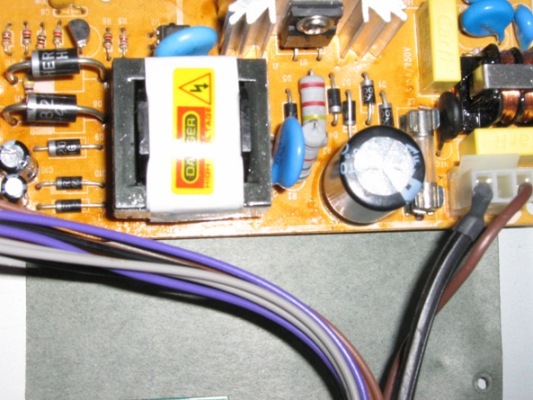 |
|
|
Gold Member Username: PlymouthCanada Post Number: 6763 Registered: Jan-08 | 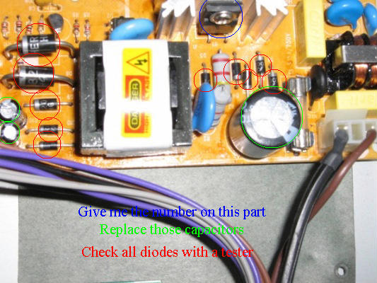 |
|
|
New member Username: Ed_fitzCanada Post Number: 8 Registered: Nov-07 |
|
|
|
Gold Member Username: PlymouthCanada Post Number: 6768 Registered: Jan-08 | Ed Fitz Replace the A5L0380R By a KA5L0380R Here is the data sheet. http://www.alldatasheet.com/datasheet-pdf/pdf/81979/FAIRCHILD/KA5L0380R.html You can check on pin 1 and 3 for C.C. voltage on 400 volts scale, do not spark. If you don't have voltage on transfo it will be this part. The square part PC817 is a opto coupler, i don't think that broke(rarely). It seems to be this part the problem: KA5L0380R. You are not bad for test your board my friend.  |
|
|
New member Username: Ed_fitzCanada Post Number: 9 Registered: Nov-07 | Plymouth: Thank you very much for the review of my info and your response. It is too late tonight to make any phone calls to obtain the part but I will check it out tomorrow after I check pins 1 to 3 for VCC voltage. If no voltage I will try to purchase it. I will revert to you in a few days and let you know how I made out with installing this part. Thanks again for your help and your kind remark to a senior. |
|
|
Gold Member Username: PlymouthCanada Post Number: 6773 Registered: Jan-08 | Ed Fitz If you have Voltage on pins 1 to 3 the part is surely broke but if not check on this 2 points in red. 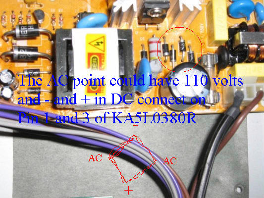 I can't see under the board but i think this is like this. |
|
|
New member Username: Ed_fitzCanada Post Number: 10 Registered: Nov-07 | Plymouth: The following are the readings on your red bridge. - To + 54.7 VAC from band of diode 2 to band of diode 3. - To + 56.8 VDC from band of diode 1 to band of diode 4. On AC setting AC to AC 54.6 VAC On DC setting AC to AC 57.9 VDC The following is a test of Part KA5L0380R On DC setting Pin 1 to pin 3 on FET 10 to 18 VDC pulsating (not steady) On AC setting pin 1 to pin 3 on FET 1.9 to 17 VAC pulsating (not steady) While I do not have a steady voltage there is a voltage. Is this part defective? I made a few calls to find the part but no one has it. One supplier checked something on his computer and said it was not available in Canada, only in USA but had no other info. Might you have another cross-reference part number or any suggestions? Please reply when you have a moment. Thanks. |
|
|
Gold Member Username: PlymouthCanada Post Number: 6776 Registered: Jan-08 | Ed This part is for 800 volts 3 amps so i don't think that is the correct voltage. Is the 400 volts capacitor is connect on this part? I found this distributor in Mississauga for KA5L0380R http://www.allamerican.com/searchresults.asp |
|
|
Gold Member Username: PlymouthCanada Post Number: 6777 Registered: Jan-08 | Here are all distributor for Canada, so i don't know if you are in Ontario. http://www.fairchildsemi.com/cf/sc_Americas.html#Canada02 |
|
|
Bronze Member Username: Ed_fitzCanada Post Number: 11 Registered: Nov-07 | Hi Plymouth, I remembered one statement you made that if the SFET was not working there would be no voltage supplied to the transformer. I decided to remove the Power board and check the voltage at the back of the board and the following is the result of this test. There was 157.4 VDC from the 400v Cap to the first set of two pins on the input side of the transformer. The SFET was supplying 159 to 170 VDC (some small pulsing) to the other set of two pins on the input side of the transformer. I now think that the SFET is ok. There was NO Voltage only small MV on the output pins of the transformer. I think I should have anywhere from 3 to 10 volts. Since the optical coupler appeared ok the other day I decided to check the CAP that connects the input of the transformer to the output side and received an OPEN on the Ohm and Diode scales for this Cap. However I did receive a reading of 1.174 VAC across this Cap. I am now a little confused since this Cap shows open on the Ohm and Diode scales but has a small voltage when checked with the power cord plugged in. Am I receiving a small feedback voltage from the optical coupler that is tied into this Cap? I am sending a picture of the bottom of the board and also a picture of the blue Cap. I do not understand the numbers on this Cap, I think it is a general-purpose ceramic disc Cap. I will have to take the board to an electronic shop to purchase one if you feel I should replace this Cap. Again thank you for your help. 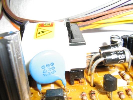 |
|
|
Bronze Member Username: Ed_fitzCanada Post Number: 12 Registered: Nov-07 | Back of board.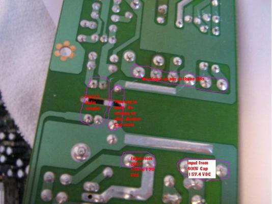 |
|
|
Gold Member Username: PlymouthCanada Post Number: 6796 Registered: Jan-08 | ED """There was 157.4 VDC from the 400v Cap to the first set of two pins on the input side of the transformer.""" 157.4 VDC is 115 Volt AC that is transfomed in DC, it will be good. A transfo can't work on D.C. voltage so you must always test it on A.C. scale. You cannot test the blue capacitor with a OHM or Diode tester, you needed a Capacitor tester for it because the capacitor lose their voltage to fast which is not as for a big capacitor with 10Mfd and more. Note that capacitor never broke and if it broke you will ear a buzz in sound. For the under board i'm not able to read nothing, you must resize the picture before and write after. Please give me the Board picture with comment i can read. You can check the transistor on right of first picture. |
|
|
Bronze Member Username: Ed_fitzCanada Post Number: 13 Registered: Nov-07 | Hi Plymouth, I finally think I have solved the problem. I did test the blue cap with the meter set to Cap and received a reading of 2.76NF. I have now powered up the board again and this time I am starting with the bridge diodes. I will refer to my first photo of the power board and start from right to left to number the diodes. The first diode on the right has 117 VAC on the band end and 64 VAC on the other end. The second diode has 0 VAC on the band end and 60.7 VAC on the other end. This I think is a bad diode. The third diode has 117 VAC on the band end and 63.1 VAC on the other end. The fourth diode has 64 VAC on the band end and 0 VAC on the other end. This I think is a bad diode. Plymouth it is a long time since I put a meter on a board so I am not as fast thinking as I was 40 years ago. Please forgive me for not having tested this board with it powered up and checking for voltage instead of doing an ohm or resister checks, which we both know often can give false results. Please be kind enough to confirm from the above voltage readings that diode 2 and 4 are defective. Thank you. |
|
|
Gold Member Username: PlymouthCanada Post Number: 6804 Registered: Jan-08 | ED Sorry but this reading seems to be OK. 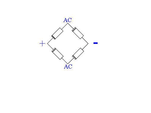 those 4 diodes are a bridge, Check on + and - on DC scale and you must have + - 140 volts DC, if you check it on AC and + you must have + - 60 volts AC. |
|
|
Silver Member Username: Jay_w_graysonPrague, Oklahoma USA Post Number: 224 Registered: Jul-08 | All Greek to me, good job guys keep up the good work.  |
|
|
Silver Member Username: King_of_satsPost Number: 638 Registered: Jan-08 | Damn it man plymouth U knows a bridge rectifer using diodes I am impress.... Unlikes king fakeman who only claims to know about electronic's u acctually do... Taking notes fakeman  |
|
|
Gold Member Username: PlymouthCanada Post Number: 6814 Registered: Jan-08 | Boba A rectifier don't use a Zener diode but a old power supply use it. That was before using of regulator. |
|
|
Bronze Member Username: Ed_fitzCanada Post Number: 14 Registered: Nov-07 | Hi Plymouth, Sorry for the delay in replying to your last reply to me. I realized my own mistake about ½ hour after I sent you the results of the diode test. I had to attend to some other business today and this evening I rechecked the board. I made the mistake of leaving one probe attached at the fuse when I should have changed it to the other AC input line and of course when I changed it I received a reading of 117 VAC. With both lines supplying the correct voltage to the diodes I went ahead and checked the output pins at the end of the Power board and sure enough they all had a voltage supply. I wish to apologies for taking up your time. However, it was a good refresher course for me after so many years. It was my first time to use the Paint program and I learned a little about that program and also how to set my camera to take a macro photo and size it so I could upload it with a limit of 100K. I feel one is never too old to learn. We have to keep our minds active. It now appears I will have to Jtag the board to get it revived. Do you have some helpful information that you could post to help me with the Jtag operation? Just a reminder the box is a Multistar MS2500PF with a 10 pin Jtag on the main board and was converted to 2700 using Puff bins before the box died. Many thanks for all your time and your help. |
|
|
Gold Member Username: PlymouthCanada Post Number: 6816 Registered: Jan-08 | Ed Good news! You are Welcome if you want help again. Sorry but maybe Nalin can help you for Jtag your box. |
|
|
Platinum Member Username: NydasPost Number: 13753 Registered: Jun-06 | [link removed] [link removed] |
|
|
Bronze Member Username: Boss_hogPost Number: 26 Registered: Oct-08 | Thank God for these two smart Fta helpers. they really know their stuff. Just watch them at work. God help us all. |
|
|
Platinum Member Username: NydasPost Number: 13755 Registered: Jun-06 | With your knowledge of electronic yu could make one easily. Don't forget the resistors. | |
|
Gold Member Username: GregrafPost Number: 1918 Registered: Dec-07 | Get your head out of the Sandman Nalin Knows Dick. Its Plymouth that has the knoledge.And leave God out of this you friggin bible thumper. | |
|
Bronze Member Username: Boss_hogPost Number: 29 Registered: Oct-08 | gregraf why do you come here and bash people that were not talking to you? what is your problem? | |
|
Gold Member Username: GregrafPost Number: 1922 Registered: Dec-07 | God told me to. | |
|
Gold Member Username: PlymouthCanada Post Number: 6820 Registered: Jan-08 | Mr. Sandman why do you come here and bash people that were not talking to you? what is your problem? | |
|
Platinum Member Username: NydasPost Number: 13756 Registered: Jun-06 | Plymouth: These people always come to ruin a thread - they come in different names. If you reply, the thread becomes a long nonsense. | |
|
Gold Member Username: PlymouthCanada Post Number: 6821 Registered: Jan-08 | Mr. Sandman Bronze Member Username: Boss_hog Post Number: 26 Registered: Oct-08 Posted on Monday, January 05, 2009 - 08:02 pm: Edit Post Thank God for these two smart Fta helpers. they really know their stuff. Just watch them at work. God help us all. --------------------- Sorry Nalin i just want return bash crying to basher. |
|
|
Gold Member Username: The_codersPost Number: 1655 Registered: Jan-08 | Bad boys reap our young girls but violet gives willingly. | |
|
Gold Member Username: The_codersPost Number: 1656 Registered: Jan-08 | Better be right or your great big venture goes west. | |
|
Gold Member Username: The_codersPost Number: 1657 Registered: Jan-08 | Bad beer rots our young guts, but vodka goes well. | |
|
Gold Member Username: DimwittPost Number: 1029 Registered: Aug-06 | Excellent troubleshooting plymouth. Keep up the good work P.S. - I like it when they chase the wild goose. |
|
|
Gold Member Username: The_codersPost Number: 1658 Registered: Jan-08 | Mnemonics A useful mnemonic for remembering the first ten color codes matches the first letter of the color code, by order of increasing magnitude. There are many variations: * Bad boys rape our young girls behind victory garden walls. * Bad boys rape our young girls, but Violet gives willingly. * Big boys race our young girls, but Violet generally wins. The tolerance codes, gold, silver, and none, are not usually included in the mnemonics 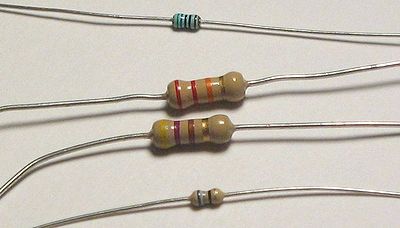 From top to bottom: * Green-Blue-Brown-Black-Brown o 560 Ω ± 1% * Red-Red-Orange-Gold o 22,000 Ω ± 5% * Yellow-Violet-Brown-Gold o 470 Ω ± 5% * Blue-Gray-Black-Gold o 68 Ω ± 5% Note: The size of a resistor is indicative of the power it can dissipate, not of its resistance. |
|
|
Bronze Member Username: Boss_hogPost Number: 31 Registered: Oct-08 | I thought they were leaving.  |
|
|
Platinum Member Username: NydasPost Number: 13763 Registered: Jun-06 | Mr. Sandman aka LK aka justforhaha's: That's your wishful thinking. The only person who has "left" a dozen times is YOU. |
|
|
Bronze Member Username: Ed_fitzCanada Post Number: 15 Registered: Nov-07 | Hi Nalin, I will have my Jtag cable in a few days. I decided to purchase one for $10.00 rather than make one. I downloaded the Full--kit 203-Puff-Femu. After I unzipped it I have one folder. When I open this folder I have 4 folders and 2 documents. I printed the two documents and they are both the same. When I open the folder named Puff 203-Femu Serial Bins I have 1 folder labeled "Doc1". When I highlight this Doc1 it is Jvvh Team Puff v203(Full Jtag) Flash, size 1 MB. When I open the "DOC1" I have a screen named Jvvh_Team_Puff_v203_(Full_Jtag)_Flash_Wall. On this screen there are a number of choices and it is here that I am lost since there is no documentation on how to proceed. Note since my box is not connected up I am receiving the following message "Could not acquire I/O. Windows NT/2K users must have administrative rights". I did download from the 2 links provided. However, the information is from 2006 and the info is not current. I would appreciate any help you can provide to me after I open the Flash_Wall program. |
|
|
Platinum Member Username: NydasPost Number: 13769 Registered: Jun-06 | I will try and look into tomorrow and might post some files or info for you. | |
|
Platinum Member Username: NydasPost Number: 13773 Registered: Jun-06 | Ed Fitz: 1. You can jtag to b60 boot Then using BL updater proceed to 294T BIN. Then do Puff conversion and then install 203V2 full EMU BIN. 2. You can directly jtag using the full jtag 203 BIN. However that might not be v2 so you should thensuperimpose the 203v2 BIN. After that you will need to do user setup, antenna setup and scan. Do not use a saved channel list. Do a fresh scan and save this list for future use. All the best. Get the jtag files and the PUFF files from the Links below. |
Main Forums
Today's Posts- Home Audio Forum
- Home Video Forum
- Home Theater Forum
- Car Audio Forum
- Accessories Forum
- All Forum Topics