Hello, I have a WS-65905 Mitsubishi rear Projection TV I bought in 2001. Recently the blue light veers upward about 2 inches from where it's supposed to be. It is something that cannot be fixed using TV's advance adjustment feature. At first, I can get rid of this problem by turning the tv off and on, but not anymore. The TV also has a problem of randomly shutting down by itself.
Do you have any suggestions? Also, does anybody have service manual for this model?
Order the manual from "servicemanuals.net" It won't tell you want's wrong, but is useful for parts location and #s. Your blue convergence output IC is going bad. It could also be shutting down the set too.
The convergence IC are normally STK series IC packages. STK-4273, or STK-4274, etc..... depending on the set, you'll have two (blue,red) and on newer sets there will be three (green) Replace ALL of them. Follow the service set up at is given in the manual.
Thanks again. I just ordered the parts. In the mean time I want to check on the PCBs itself for any cracks on the solder joint. Any idea how to remove the CRT PCB from the tube? I removed one screw that fastened the black plastic strap around the bottom of the tube. I also removed some of the grey putty-like cement (should I?). The PCB still won't move. Any idea? Thanks.
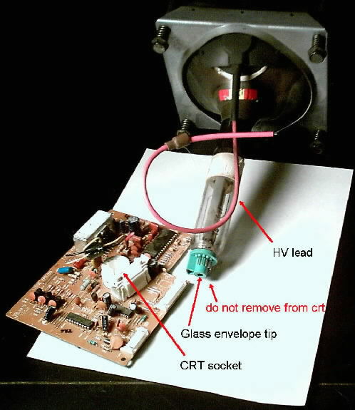
Ya, the silicone glue has got to come off the socket. Use a knife to cut the glue between the colored pin housing and white socket, that's where it separates. You've got the neck strap loose, good. Now rock the crt drive board back and forth ever so slightly. Get you fingers as close to the socket as you can. Pull straight back. Don't rock the board more than a couple of degrees. There is a glass tip inside the crt socket housing. The crt pins can be bent without causing any damage, because they're made out of a soft metal and you can bend them back without breaking one off. The glass tip in the key way of the socket is pretty sturdy, but if you break it the crt is trash. Got to go, wait and I'll post a pic
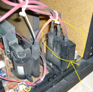
Steve, thank you. That's very helpful. I'll dismantle it next week. I'm just wondering, when removing the main PCB from the cabinet, can if I disconnect four thick cables (or are they pipes? that connect to CRT tubes) from the CR block located on the near right hand side of the main PCB?
Hi guys. Since we are on 65905 subject. I just picked up a used unit that peole claimed wont power up after they moved. I plugged it in... and i can hear the relay click on the right side if you stant behind it. Have not taken it apart yet. Just started reading and most of theese sets had the same problem of solder cracking. Kinda makes me think this would be the area where i could start before the service maual comes in. Any suggestion would be appreciated
Steve, I'd like to thank you for the assistance and also all other member for their inputs. I fixed the TV last night. You're right; turns out the outer four pins of each STK chip were cracked. So I changed the STK chips and reflowed all the joints/connectors. The TV is good for now and I don't even need to remove the red HV cables.
I'd like share one thing. There are three screws that hold the heatsink in place. The screws are tightened (through PCB) into the plastic tray/frame. I notice that the two outer plastic holes were badly cracked, maybe due to over-tighten during assembly, causing the outer pins of the STK to bear some of the heatsink weight. I suspect this may contribute to the cracking of the solder joint.