Sunfire True Subwoofer pops
|
New member Username: DrdaveelectFlorida Post Number: 2 Registered: Nov-09 | We have a Sunfire subwoofer in for service. After replacement of many capacitors, the unit seems to work fine except for an occasional loud pop or thud from a normal audio source ,but with a steady low freq. test tone it work without any pops .Any ideas? Someone said it maybe switching intermittently in and out of standby on normal audio.We don't have any service info on this so it makes life even harder. As always any help would be appreciated |
|
Gold Member Username: JrbayLivonia [Detroit area], Michigan USA Post Number: 1028 Registered: Feb-08 | Greetings Dave, Can you recreate the problem? If it only happens at a low volume level then the auto on circuit is certainly one place to look. If the threshold is too high obvious problems could occur. The auto on should make a relatively distinctive sound and perhaps could be targeted or eliminated on that alone. I am not sure how far you are into this and I may be tossing very elementary ideas out but if it isn't the auto on then I would check all grounds very carefully. |
|
New member Username: DrdaveelectFlorida Post Number: 3 Registered: Nov-09 | Thanks for your input Jim, On an audio source I get the intermittent pop or thud noise more often on voice or when their is a break in the low frequency content. The level control does effect on how loud the pop is and when the control is all the way off ,no pops. Like I had mentioned with a low freq. test tone of any level no pops ever. When the unit goes into standby the LED is to go dim .If I kill the audio input it will time out and go dim. I'm not seeing that happen when it's playing.So i'm not sure if this a standby problem. |
|
Gold Member Username: JrbayLivonia [Detroit area], Michigan USA Post Number: 1031 Registered: Feb-08 | With that perhaps it is possible to put stand by/auto on aside. The next thing is the source as in can the noise be recreated with different sources? If so, I would head back to the grounds and seeing if I could find ANY resistance anywhere. I may be way off base but my experience (mostly automotive) has been that low level noises such as these are some sort of bad/poor ground. |
|
New member Username: Port3f8Los Gatos, CA USA Post Number: 1 Registered: Mar-10 | I have the same problem, and have just about finished reverse engineering the power amp board on my Sunfire true sub. I finally have found the components that set the timing for the auto on-off. Interestingly, most of the schematics are very similar to Bob Carver's original patent - but the auto on-off circuit is not in the patent (#5937074). I am not going to post Bob's schematics, as I feel that would be unfair - his patent has not expired yet. However, I can say that the auto on-off time is set by a single resistor-capacitor combination. R40 and C18. These are 5.2 megohms and 22uF. You will find these at the bottom-left corner of the quad jfet opamp U2 (MC34004). The 22uF cap looks to be a higher quality that all the other electrolytics. Another interesting thing is that the most complex integrated circuit in the whole sub is an opamp. There are only opamps, comparators, and discrete transistors (fets and bipolars). By the way - my negative13v rail turned out to be bad, giving roughly 8v DC, due to bad electrolytic caps - and this was throwing off the auto on-off threshold. I also blew out my pnp devices in the output stage, so just ordered some replacements. Let me know if you have any additional questions, and I'll hopefully be able to point you in the right direction. |
|
Platinum Member Username: NuckPost Number: 14729 Registered: Dec-04 | Welcome to the forum, port! That's #1 opening post of the year! most of us here don't get too technical, but you guys should be all set! Dave, sorry I missed your OP. Are the opamps replaceable port? |
|
New member Username: DrdaveelectFlorida Post Number: 4 Registered: Nov-09 | Port, Thanks for the info. We did find a bad 1000 mfd. cap in one of the power supplies that we overlooked the first time around. All is well. Thanks again. |
|
New member Username: Port3f8Los Gatos, CA USA Post Number: 2 Registered: Mar-10 | Yes, the opamps are just cheap motorola jfet quad opamps. There is nothing in the electronics that cost more than $2. Even the power npn & pnp devices. A WORD OF WARNING though: anyone that opens up this sub - beware. The power supply caps on this board and on the back-plate can retain 100s of volts for literally days. You can get around a 300V shock. I only know this, of course, because I got shocked 2 days after it was last plugged in. Live and learn eh. I'm so used to working on 5v stuff. |
|
New member Username: Port3f8Los Gatos, CA USA Post Number: 3 Registered: Mar-10 | I forgot to mention - if you want to completely disable the auto on/off, do this: pin 6 of U2 quad opamp is used as a comparator with some feedback hysteresis. The RC timer goes onto this pin. It looks like it gets charged to the negative 13v rail when in the 'on' state. Simply short it to pin 11 of U2 (-13v) and the sub should stay on permanently. To be safer, use a 10k resistor from pin 6 to pin 11. However, I have not tested this. Will update when I get the sub back together. |
|
Gold Member Username: DmitchellOttawa, Ontario Canada Post Number: 3731 Registered: Feb-07 | Holy crap port, you know your stuff. |
|
New member Username: Port3f8Los Gatos, CA USA Post Number: 4 Registered: Mar-10 | I am still waiting on new bipolar power transistors, but I did do a 1kohm load test on the -13v rail before and after replacing the electrolytic filtering caps. The old caps saw a voltage droop of around 3v with a 1k load, and the new caps show no noticeable droop. I also verified on an oscilloscope that the RC timer does indeed go to -13v and then slowly start charging up in the absense of an audio signal. So, to disable auto on/off, my previous post should still be correct. I also marked the caps that should be replaced. Might as well do all of them if you get in this far! 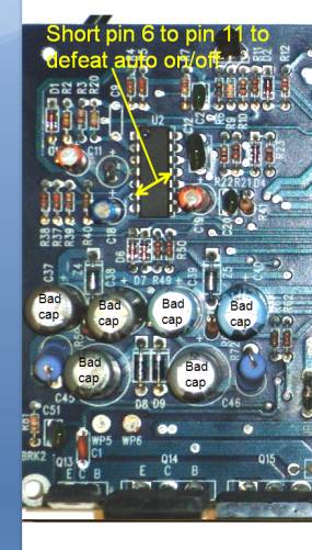 |
|
New member Username: Rubli,, Mexico DF MEXICO Post Number: 1 Registered: May-10 | Hi I have one of this beasts on my working table, I am preety frustrated. I have full (negative) voltage on the negative output transistors collectors, but only 13 volts on the positive collectors, I have replaced all fets. I guess that the malfunction is on the negative downconverter, and not in the upper downconverter. unfortunately the schematic I have is only close . I wonder if there are several versions... any hint will be deeply appreciated. regards Alex |
|
New member Username: Port3f8Los Gatos, CA USA Post Number: 5 Registered: Mar-10 | Hi Alex, Could you clarify what you mean by full negative voltage? There are three sets of supply rails: The low voltage rails: + 13v, -13v The class D tracking rails: which are somewhere between the 13v and 160v, And finally the bridge rectified and filtered line voltage, which I measured around +160v and -160v. There is a 4 wire connector that has signal, gnd, -13v, +13v. You could check those first? |
|
New member Username: Rubli,, Mexico DF MEXICO Post Number: 2 Registered: May-10 | Hi, thank you for your input, sorry for not being clear... I have checked the low voltages supplies (+/- 13v) they are OK on the source of the negative IRFS's I have -140 volts, on the source of the positive IRF's I have 13 volts. I the schematic I have , as I mentioned is not of the one unit I have, instead of the quad LM339 (in the downconverter sections) I have an A211 optocuipler which is driven by a BA10393 comparator. As far as I got, is to determine that I have a high frequency oscillation on the output of one of the BA10393 sections (in pin 7 that goes to the diode's optocoupler, which is pin 2), that is in the positive side, but on the negative side (that is output pin #1 of the comparator), there is no such oscillation , I will be replacing this chip. I have replaced the small TO92 transistors(whose diferential output drives the IRFS's) they were leaky.(on the negative side). any comentaire will be appreciated. (forgot to mention, I am troubleshooting the unit with a lowered AC voltage, something around 90 volts) thanks again regards Alex |
|
New member Username: Port3f8Los Gatos, CA USA Post Number: 6 Registered: Mar-10 | Hi Alex, I will dig up the reverse-engineered schematics tomorrow as I left them at work. As I recall though, the high power output fets( nmos for both rails) connect to the bridge rectifier rails via a couple of fuses that actually look like resistors, and are soldered onto the board- not removable. When the fets blow up, they usually short circuit, hence the fuses. There are a couple of replaceable fuses on the power amp board too - one for each high v rail, but I assuming you've checked those. |
|
New member Username: Rubli,, Mexico DF MEXICO Post Number: 3 Registered: May-10 | Hi, Thanks again... there are a pair of jumpers on the location you mention that there are fuses like resistors, I put a pair of 10 ohm 1/4 resistors instead (underneath meanwhile), maybe they are too high, but I already blowed a pir of OPT... thank you for your support regards Alex 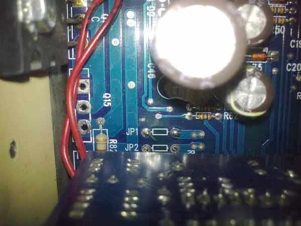 |
|
New member Username: Port3f8Los Gatos, CA USA Post Number: 7 Registered: Mar-10 | Yes, those are the ones: JP1and JP2. 10 ohms is much too high. The bipolar class D transistors can run at over 20 amps, so these need to be down in the milli ohms. I blew both mine too, so I do not know what their exact values need to be, but assuming a 1v drop at full power gives 0.05 ohms. The 4 diode string that biases the class AB output stage can also get blown out, leading to further destructive powers! |
|
New member Username: Port3f8Los Gatos, CA USA Post Number: 8 Registered: Mar-10 | Hi Alex, Both positive and negative class D power rails are formed by a couple of buck regulators, and both use nmos power fets. This means that the source sides of the powerfets are different: the source of the positive rail will be the switching node of the buck, and if it is inactive, it will be a low voltage like +13v. However, the drain side of this fet should be 140v. For the negative rail, the source side will be -140v, and the drain side will be a lower -13v or even -6v. Bob Carver is able to use nmos devices for both rails as he is 'boot-strapping' 'flying capacitors' to provide isolate gate drive for each rail, and opto-coupling the drive signals to eliminate the dc-coupling problem. Anyhow, check the drain and sources - they will be inverted voltages and drain-source swapped for each of the two rails. |
|
New member Username: Rubli,, Mexico DF MEXICO Post Number: 4 Registered: May-10 | Hi thanks for your input, I am trying to solve why I have -140 on the negative collectors on the (2SA2121) output transistors , which according what you tell me should be somewhere around -10 volts. i checked the drain and source (respectively) and they are OK, +140 and -140 I am still waiting for the BA10393 to replace... does your schematic have 2 BA10393 or 1 LM339 on this section ? thanx again !! Alex |
|
New member Username: Port3f8Los Gatos, CA USA Post Number: 9 Registered: Mar-10 | Hi Alex, I am unable to output from my computer, so had to take a photo of the screen. Here is the output stage transistors: 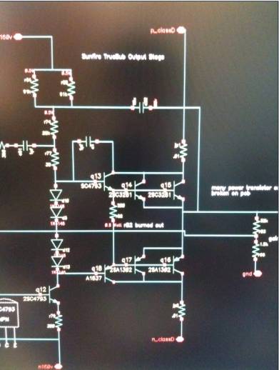 when I get a proper file, I will upload it. |
|
New member Username: Rubli,, Mexico DF MEXICO Post Number: 5 Registered: May-10 | Hi Thanx for taking the time to make a picture of the screen !!! It seems that the schematic you have is closer to the unit I have : the schematic I have looks like this: 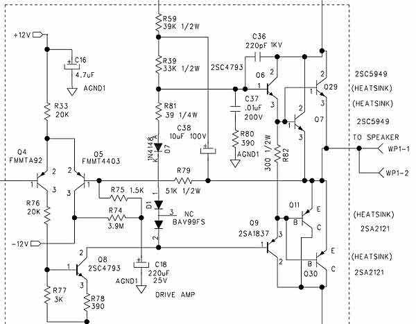 it would be easier if I send you the schematic I have , so I can pinpoint where the differences are, or if you agree to send me yours... my email is alex..rubli.net (replace .. with you know what) I can't thank you enough for the help, sunfire stopped me responding after sending me the schematic , which is not the revision I have best regards Alex |
|
New member Username: Port3f8Los Gatos, CA USA Post Number: 10 Registered: Mar-10 | Yours looks closer to their patent app- with a 3 diode bias string. Mine has 4 n4148 diodes. Our computer tech guys are out today- as soon as I can connect my unix box, I'll get you a better, larger schematic. |
|
New member Username: Rubli,, Mexico DF MEXICO Post Number: 6 Registered: May-10 | Hi I am still lost, I changed the suspicious BA10393, but I don't see any high frequency comming out from either output of the chip. I can't do more without its shematic, as I said, I have anoher version of it help... regards |
|
New member Username: DlathamPost Number: 1 Registered: Jun-10 | I am working on a Sunfire True Subwoofer I've replaced a bunch of caps and it seems to be working ok but I get a LOUD pop when I unplug it. It seems to be coming from the tone control board and not the power amp board. Any ideas? Also I got a schematic from sunfire they were willing to give it to me because they no longer service this model, so it might be worth asking them for one. Thanks |
|
New member Username: Vette45Post Number: 1 Registered: Mar-11 | Dave P, Looks like I have the exact same problem as yours with my True Subwoofer. i.e. the unit works as normal when the volume is crank all the way up. But when the input signal gets low or if the sub volume is turned down, then the unit will make loud pop until steady high volume sets in again. So did you resolve your problem? If so, can you please share your solution? Port3f8, After reading your replies, it seems like you really know the amp circuit of this subwoofer inside out. Can you please advise on how to repair this unit for my condition? Should I replace those 6 cap as mentioned in your post #4 above, will that solve my problem? BTW, can I get those components from local Fry's? If not, where can I get those locally?(I'm local in the Bay Area as well). Can't wait to get the subwoofer fixed. Thanks for your help in advance. |
|
New member Username: DrdaveelectFlorida Post Number: 5 Registered: Nov-09 | I think all my problems were solved by replacement of caps in the +/- 12 Volt supplies. I think C-18 was one of the caps that made a difference. It has been a long time since I serviced that Sub ,and hope it's my last. I'm sorry I don't have more for you on this. Any good parts house should have the caps. If not you could order from MCM electronics. Good luck! |
|
New member Username: Vette45Post Number: 2 Registered: Mar-11 | Hi Dave, Just want to confirm with you on which caps that you have replaced to get the unit working again. So did you just replace those 6 as labeled as "bad cap" in the picture from Port3f8 in his post number 4? Plus C-18 that you've mentioned? Thanks. |
|
New member Username: DrdaveelectFlorida Post Number: 6 Registered: Nov-09 | Like I said It has been a long time since I serviced that Sub .To be safe Replace C-16, C-18 and the six that someone else had mentioned. Good luck. |
|
New member Username: KerebrosalphaPost Number: 1 Registered: Apr-11 | I have some really big problems with my Sub woofer. It originally was giving burps in the sound. now the sub doesn't properly work. it only moves forward and is very distorted with no bass and blows the on board protectors in the process. the internal fuses are for some reason 10 amp Slo-blo instead of 10 amp fast acting. Also, the JP1 and JP2 aren't blown. Any idea what causing this issue. I'll try to post an oscilloscope view of what the output looks like on a 100 - 5 hz sweep. |
|
New member Username: Rubli,, Mexico DF MEXICO Post Number: 7 Registered: May-10 | good luck ! there is no troubleshooting guide I could give, there are two different "grounds" this is the fist thing you have to understand. there are some caps that go bad,(already mentioned here) , in my case, some optocouplers (HCPL-2611 )that aslo got bad, that are listed as op amps in some variations of this schematic of this sub. (I relapced them with 6N137) hope this helps..send me a PM and I can send you my version of the schematic (which by the way did not correspond to the unit I had... |
|
New member Username: KerebrosalphaPost Number: 2 Registered: Apr-11 | HOLY CRAP. I found Coil L1 was broken at one end so i soldered it back on. the moment i plugged it in, the thing made A VERY LOUD POP. Also, the main 10 amp Slo-Blo fuse on the outside now looks like this. 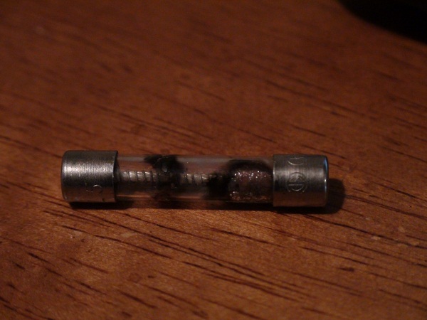 |
|
New member Username: KerebrosalphaPost Number: 3 Registered: Apr-11 | The FPI4020 Bridge rectifier(200 volt, 40 amp) was blown...no current...Forward and backward on all poles.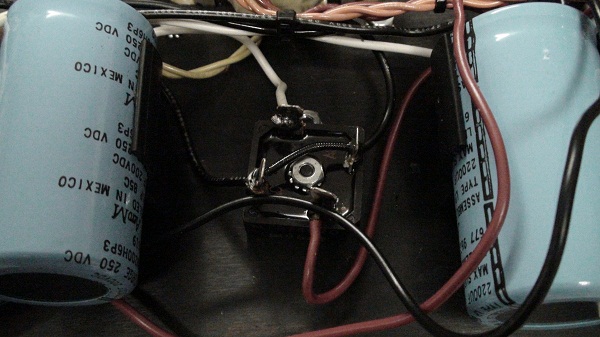 I'm heading out to get some new ones tomarrow. also, i'm going to check c-16, c-18 and other caps for possible damage. should i bother checking the transistors for problems? 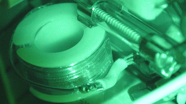 this was my repair on L1...Yeah for real. |
|
New member Username: KerebrosalphaPost Number: 4 Registered: Apr-11 | replaced that Bridge rectifier. Didn't go over so well. We were stupid enough to plug it in and the Power transistor 2SA1302 Died.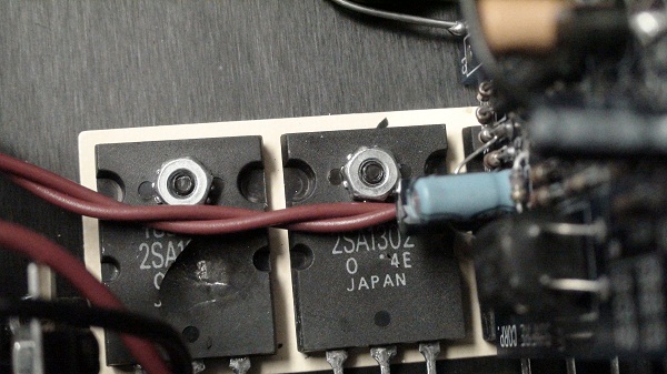 I'll be replacing all the Transistors on this unit in the next couple of days. |
|
New member Username: Rubli,, Mexico DF MEXICO Post Number: 8 Registered: May-10 | check also the hexfets.... |
|
New member Username: KerebrosalphaPost Number: 5 Registered: Apr-11 | Which are those? I'm replacing ALL transistors. Should i worry about the LM's?(8 pin IC's) |
|
New member Username: Rubli,, Mexico DF MEXICO Post Number: 9 Registered: May-10 | according to my schematic and the unit I repaired, there are 6 TO220 IRF640 transistors, that might be a good idea to check'em out good luck |
|
New member Username: Jlnorie2Oak Park, IL USA Post Number: 1 Registered: May-11 | What a great resource this is! Just wanted to report that I followed port3f8's advice on how to disable the auto on/off by shorting two pins on the 'U2 quad opamp' - using a 10k resistor (posted on March 15th & 19th)... And it worked like a charm! My unit would start 'clicking' whenever there was no low frequency signal going into it; the clicking would stop as soon as the signal returned but once the unit had been on and working - the clicking would continue even if all other components had been turned off; and even if I disconnected the signal cable!. Since the MKII doesn't have an on/off switch/button, I would have to disconnect the power to make it stop... After following the procedure described by port3f8 the unit is now working as it should and shaking the paint off my walls! Of course, now the unit is always 'ON' but I decided to use a cheap monster power distributor which I can turn off when I'm through using the Sunfire... Thanks for your invaluable advice! |
|
New member Username: KerebrosalphaPost Number: 6 Registered: Apr-11 | Oh yeah, should i replace the U2 Quad OPamp or leave it. Cause we can't get parts till our supply center gets the shipment of parts we put in. |
|
New member Username: Gxt6551Post Number: 1 Registered: Oct-11 | Hey, I am new here. I hope someone could help me out! I got a sunfire EQ 12 true signature subwoofer from Craigslist. It worked great at beginning. However, the issue is auto off. It will turn off after a few minutes no matter for movies or music. The led light is off completely. I need wait about 15 minutes then can switch it on. Is there anyone with the similar issue? I try to disable the auto off function as port3f8 said in this thread, but I could not found the U2 quad opamp as showed in the picture. Does sunfire EQ 12 have the different power amp board as the true sub discussed in the thread? Please help out? Thank you so much! |
|
New member Username: KsdehoffPost Number: 1 Registered: Jan-13 | Port3F8 are you out there! I've just come across this post and am deep into the repair - in addition to the 4 caps at c37-c40 being bad (all of them) and C18, I've also got a 21 ohm 2 watt resistor at R8 bad (visible signs of a burn. My symptom is that the sub pops when it transitions soft to loud. I've got a cap tester and am wondering if I need to look at anything beyond the caps pointed out in this article. |
|
New member Username: NathanielPost Number: 1 Registered: Mar-13 | Hello, I'm new to this board and I'm a novice in board component repair. I have one of these subs and last month the sub just started to make an audio poping sound over and over even with the audio cables removed. Then both fuses blew blew on the board. I replaced the 6 caps (shown on this thread) and the board fuses and then when i plugged it in the main fuse blew. I replaced the bridge rectifier and the main fuse. But I then when I plugged it in this time, with the board were I can see the circuitry, I could see that a mosfet had sparked. The GFI outlet tripped but the main and 2 board fuses didn't blow this time. I removed the bracket and 4 of the 6 mosfets are cracked and the one was a bit toasty. Any idea what would have caused these to blow? Nothing else looks blown/ burnt on the board. The 6 mosfets are SEC 711 IRF640 but I don't know if it's an N or P well. Do you all know? I found some on ebay but I'm not sure if these will work. http://www.ebay.com/itm/IRF640-TO-220-Mosfet-10pcs-/400044471669 Thanks for any help Nathaniel |
|
Gold Member Username: MagfanUSA Post Number: 3024 Registered: Oct-07 | Go to the IR website and enter the data and you'll get more information than you need....or probably want. But it WILL tell you if the device in question is nchannel or pchannel. IR has a MAJOR plant in Temecula, California which is PROBABLY where the device was manufacturered....and packaged down south in TiJuana. PS: the IRF640 is an Nchannel device. This is a commodity device not worth more than 1.10$ per thru something like DigiKey. |
|
New member Username: NathanielPost Number: 2 Registered: Mar-13 | I'm sorry what website? |
|
Gold Member Username: MagfanUSA Post Number: 3026 Registered: Oct-07 | IR = International Rectifier........they make the part in question. Also, I believe that this is a legacy part which was SOLD to Vishay....so they made a bunch before production ceased.... It's called a 'build out'. I suspect it is an 'obsolete' device and is no longer made by 'primes'. They will be available for several years....or longer....yet to come.... Vishay and IR had an agreement for a couple years in which certain technologies and designs were transferred to Vishay. |
|
New member Username: NathanielPost Number: 3 Registered: Mar-13 | So is there no other mosfets I can replace them with? I know I need 6 TO220 IRF640 transistors but I don't know the rest of the specs, if it's an N or P channel and the voltage and amps. Can anyone provide a link to the part on http://www.mouser.com/ ? Thanks |
|
New member Username: RevertPost Number: 1 Registered: Jun-13 | Great thread. Years ago when these first came out I was the guy in MN who would have to send these in for repair. Back then no one could work on them, I was a service tech, but I had to send all amp modules back to the factory. Now I finally got my hands on one to repair. This was an Architectural series Truesub. Customer said it would cut in and out. He must not have been too attentive, because this thing had a huge hum and was only processing part of the input signal. Right away it sounded like a capacitor issue to me, and so it was. I replaced the two 2200uF 25V caps on the power supply and the unit no longer has a hum, and is pounding away in my living room. Now I just don't want to give the repaired unit back... :-( |
|
Gold Member Username: MagfanUSA Post Number: 3045 Registered: Oct-07 | IR = International Rectifier. http://www.datasheetcatalog.org/datasheet/SGSThomsonMicroelectronics/mXqsuu.pdf Part is Nchannel MOSFET. and it Does appear to have been transferred to Vishay...but they will be equivalent part. |
|
New member Username: RevertPost Number: 2 Registered: Jun-13 | I was just able to acquire one of these for my very own after drooling over them for 15 years. I bought it for $200, because the unit had the normal 60 cycle hum. Nor problem I thought, replace the 220 uF and the 1000 uF caps and I'm all set. Opened it up, caps looked fin.e, replaced them anyways, and still had the hum. Took it apart again and took a closer look. I forgot exactly, but I think it was C13, 470 uF 25V caps right next to a voltage regulator on the signal input board. Replaced one, sealed it back up, and now I've got it pounding away in my living room as I type this. No hum. So there you go guys, if you have issues with these, replace the low voltage filter caps too, @ $0.80 it's not a bad idea. |
|
New member Username: Audiorep1013nsRichmond, VA USA Post Number: 1 Registered: Oct-13 | I need a big favor from, I have a Sunfire TS-SJ8 Subwoofer. I removed the 2 big Transistors 2SAxxxx and 2SCxxxx PNP & NPN transistors and I don't remember which one goes where the location # is Q7 and Q11. If someone knows where I can find the schematics I would appreciate it. Thank you so much |
|
New member Username: KerebrosalphaPost Number: 7 Registered: Apr-11 | Hello, I have a TrueSubwoofer, REV A board. Look at my pics above, mine goes left to right 2SA 2SA 2SC 2SC |
|
New member Username: BondjbondPost Number: 1 Registered: Oct-13 | Hello everyone, I have exactly the same situation described by Nathaneil in his post at 03/25/13. I have replaced 6 bad Caps and blown fuses, after I plugged it in, the third MOSFET from the left blew up, the fuses did not. Could anybody help with what causes this and what would I should be looking to replace to fix this issue. Any help will be greatly appreciated. Thank you. |
|
New member Username: KerebrosalphaPost Number: 8 Registered: Apr-11 | I gave up on mine finally. You might as well too. I took it to 5 repair shops, all of them said they could do it, and gave me a call back 2 months later saying they gave up too, and i would be better off just plating the side and using it passively. To directly answer your question, no one really knows what causes the issue you described. For us, there's 6 smaller transistors that were all blown on the other heat sink. IRF640 I think. Then the 3 small transistors near the power transistors. But hell, I'd like to see you try fixing it. I've had this thing for 3 years, and over 2 years, i couldn't do it. Only reason I gave up is i ran out of spare parts in my parts bins. |
|
New member Username: RevertPost Number: 3 Registered: Jun-13 | I may be interested in buying the dead ones off of you guys if the price is right. Shipping cost might suck, but if they're just collecting dust from now on I'd like to have them around. Let me know. |
|
New member Username: BondjbondPost Number: 2 Registered: Oct-13 | Dear Kerebros, thank you for your thoughts on the subject. I have ordered MOSFET's, rectifier and will give it one more shot. If this does not work I may follow up your steps, but this is just a matter of being persistant and make god gamn thing work. Sincerely, |
|
Gold Member Username: MagfanUSA Post Number: 3104 Registered: Oct-07 | Link to data sheet for IRF640�½..Now, as I said before, made by Vishay. This is a COMMODITY part and should be inexpensive if not downright cheap |
|
New member Username: KerebrosalphaPost Number: 9 Registered: Apr-11 | I gave Up on my Sunfire. I plated the side and made it a passive sub. Made a home made Class A low FREQ Cube amp(about the size of a 8x8x8 box), rated at 400watts at 4 ohms single channel with <.005THD and high dampening factor. So far, it's running really well, and tbh, i think it's responding better below 35hz than the stock amp. However this thing needs tweaking. Might try and repair my sunfire's amp one more time, but the board has so many blown traces and what not, i have more wire than trace now. |
|
New member Username: Navaบางใหญ่, Nonthaburi -... Thailand Post Number: 1 Registered: Aug-14 | Hi I have the Sunfire subwoofer mk II in for service too, a symptom was the unit have no sound. I found the power transistors and mosfet were shorted, I replaced 4pcs power transistors and 6 pcs mosfet but still not work. Can anyone suggest me. Thank you |
|
New member Username: NathanielPost Number: 4 Registered: Mar-13 | Sunfire is crap! After my attempt in fixing this over priced piece of $hitt and spending $60+ in parts it still wouldn't work. I threw mine in the trash where it belongs. |
|
New member Username: Navaบางใหญ่, Nonthaburi -... Thailand Post Number: 2 Registered: Aug-14 | I forgot to mention the unit has DC voltage at output of power amplifier about 35Vdc when plug in the ac cord. Also I measured the 140V power supply, +140V dischared faster than -140V. |
|
New member Username: HecklerzPost Number: 1 Registered: Mar-15 | Hello, Anyone have some advice on repairing a Sunfire TS-EQ10 that powers up fine, no blown fuses, but no sound output. It shooshes when I power it on and everything seems fine but no matter what signal I put into it I get no output whatsoever. When I touch the RCA to the input I do get that hum. !!!!!!Please advise!!!!!! |
|
New member Username: AudiodoctorcanadaPost Number: 1 Registered: Mar-15 | I repair and will buy defective units that have not had failed repair attempts. (Its easy on these to make the damage worse attempting repairs to downtracker) drop me a line s_vares@hotmail.com |
|
New member Username: Munchkinsandwich2Post Number: 2 Registered: Mar-15 | Hi everyone, Thanks for the info. We find a bad 1000 Ic. cap in one of the power supplies that we overlooked the first time around. All is well. Thanks again. |
|
New member Username: BraineePost Number: 1 Registered: Jul-15 | Hi guys. I'm desperately seeking help to fix my Sunfire D-10 subwoofer. Bought it second hand, opened it and found out that C13 and R3 are burned. Subwoofer is working but I'm afraid that it might cause some problems later on. Does anybody have a schematic? Or at least any idea how to fix this. |
|
New member Username: Kevc711Post Number: 1 Registered: Nov-15 | Hello everyone, Hopefully this thread is still active. I recently purchased a Sunfire True Sub MK iv. I am replacing the power caps (200v 1600uf) but I can not at all remember or find where the jumper wires go to. Can anyone at all either tell me where they go or upload an image of where they go? All the ones I find online are overhead shots that don't help at all. Thanks so much! |
|
New member Username: TonebellsFL Post Number: 1 Registered: Mar-17 | https://www.ecoustics.com/electronics/forum/home-audio/618938.html#POST1861785 JP1/JP2 are 0 ohm resistors. |
|
New member Username: ScrotorWest Sacramento, Ca United States Post Number: 1 Registered: Jun-17 | Greetings all! So a friend brought one of these sunfires to me to look over an if possible repair. They stated no power. First thing that caught my eye was 4 caps mentioned in this thread, the tops were bulging. After replacing, still no power. I then ohm out infinity on the fuse holder and noticed the fuse cap never engages when rotating - bad fuse holder replace. power restored. PRIMARY QUESTION: When doing a test on each left and right channel separately, i get a lower amplitude output when testing just the right channel. Left is greater in amplitude however. When reading the manual, it states that if using only a mono input, use the Left channel, and bridge the right.... leading me to wonder if the lower output from just inputting to the right channel only is normal? |
|
New member Username: Ranman57Post Number: 1 Registered: Feb-18 | Hi All! I just thought I'd throw this out there for anyone who wants to try out the trigger bypass concept. I recently brought my Mark IV out of retirement to use in my office as it seemed silly to just let it sit in the basement doing nadda. Due to the wiring in my office being part of a whole house audio system I need to run it from the speaker level inputs. The problem was since I rarely play the audio in there very loud the thing only turned on sporadically at best. So I tried the bypass with a 10K resistor and confirmed that works great. I then went looking for a relay to use as a 12 volt trigger and found the CZH-LABS Electronics-Salon 1PCS Dual SPST-NO 10Amp Power Relay Module, AC/DC 12V Control Voltage on Amazon as I wanted a sealed relay that could take the pounding inside the sub's cabinet. Here's where it gets kinda fun. When I went looking for a good place to mount it I noticed two screws in the middle of the plate that in my rev of the amp don't do anything, they must have been put there for some other future purpose or whatever. As it happened they match the mounting holes on the relay exactly, and with a little pushing around of wires the relay fits in there like it's factory installed. I used a 5.5mm panel mount power jack to get power to the relay as I couldn't find a sealed back 3.5 phone jack that seemed sturdy enough. So in the end it all works great. The sub's on its second recapping at this point, and will surely need it again some day, but for now it's a great addition to the office setup. I hope this helps anyone who wants to manually control their sub... |
|
New member Username: SubboPost Number: 1 Registered: Aug-18 | I know this thread is ancient, but I have been re-capping these subs for a few years, the secret seems to be to replace the caps with larger values than the ones chosen, then they don't seem to fail again. Any that I re-did with the same values lasted a couple of years before failing again. I also think that maybe moving the amp outside of the box, and having a new blank plate fitted may let the components last longer. |
|
New member Username: JozefpPost Number: 1 Registered: Aug-18 | Does anyone know if the short of pin 6 to pin 11 of U2 will work on a True Subwoofer Signature? While I found U2 on the True Subwoofer Signature, the surrounding layout does not match what port3f8 provided above. |
|
New member Username: CreatoPost Number: 1 Registered: Mar-20 | Hello all, seems this thread died down, which is a pity because Sunfire subs are also still dying. Since there is NO support anymore for these subs, does anyone care to share the schematics???? As for me I have an EQ Signature in repair, and I will share my finding & fixes when I get the schematics through this forum... Let's help each other out...Thanks! |
|
New member Username: Jorge_pachecoPost Number: 1 Registered: Apr-20 | hello i have a problem with my true subwoofer super junior 8" tried to find the circuit diagram but couldn't find it I want to know what kind of transistors the audio output has, I show the imagen 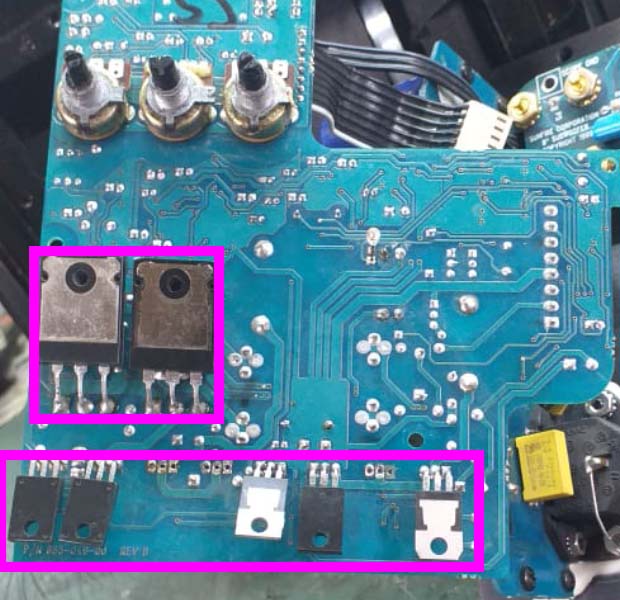 |
|
New member Username: MarianreggaePost Number: 1 Registered: May-21 | buenas noches, estoy intentando reparar un sunfire true subwoofer junior. alguien tiene le diagrama ? lo pedi a carver pero no tengo respuesta todavia ... tengo problema con los irf640 . y unas resistencias smd quemadas |
|
New member Username: Allene222Palo Alto, California United States Post Number: 1 Registered: Jun-23 | What a great thread. I am going to try and repair our True Sub as soon as my son brings it back. The reason I am writing this is to share a schematic that is closer to the description above. One thing of interest in this version of the schematic is the inclusion of a jumper (J2) that basically connects pin 6 of U2 to pin 11 through a 10K resistor just as described in the text above. Our sub has a loud pop when it turns on. It drove me crazy so I gave it to my son and it is driving him crazy. He says there is a faint noise as well. By the way, I found that there is a hum if the unit is plugged in one way and that goes away if the 120volt plug is reversed. I will update this if anyone cares these many years later. https://thecarversite.com/manuals/Sunfiremandir/Sunfire%20Schematic%20Subwoofer% 20Suspected%20-%20NHT.pdf |
|
New member Username: Allene222Palo Alto, California United States Post Number: 2 Registered: Jun-23 | Well, I put the resistor across the standby op-amp and that really fixed the issue. No more standby and the unit sounded and tested great. My son took it home and it worked great... until the next morning. Apparently leaving it on all night blows out some of the output transistors or something. I guess they got too hot. There is no positive output and the negative output is only the peaks of the waveform. I guess we will throw it out and buy something else. Just wanted to follow up in case anyone cares. |
|
New member Username: Stevens54Post Number: 1 Registered: Jul-23 | Yes I agree this is a great thread. Thanks for posting a link to the schematics. I have been searching everywhere for them. I am waiting to be approved before I can actually view them. Sorry yours quit working on you. If you are going to throw it out I would gladly pay for shipping to have it as a spare for mine. Maybe between the two I could get one to work. |
|
New member Username: Stevens54Post Number: 2 Registered: Jul-23 | I have now been approved but the link you posted no longer works. Could you post a copy of the schematics if you have it please? |
|
New member Username: JpwolfSequim, WA United States Post Number: 1 Registered: Apr-24 | Has anyone accomplished turning off the wake-up pop on the True Subwoofer? It seems like it should be easy since other brands of subs have the feature to switch the trigger off so that the sub stays awake, but apparently shorting pin 6 of U2 to pin 11 through a 10K resistor is NOT the solution. |
|
New member Username: RhymeswboPost Number: 1 Registered: Apr-24 | hello, just fixed my signature sub. Thought id report on it, as this thread was very helpful to me. I replaced all the larger caps, but this was not the immediate cause of any of my problems. 2 problems fixed. 1) rca inputs were intermittent. worked ok sometimes, but sound would degenerate into random oscillation only loosely related to audio after a few minutes. Cause: bad solder joint on the audio signal ground wire from the input card to the RCA inputs. looked fine, looked fine on a multimeter sometimes... but "wiggle" testing led me to the problem. Fix: solder fix. 2) similar to many on this thread... trouble coming out of standby/low power. symptoms. glitchy noises when turning on, worse with low (or low-base) input. sometimes click/glitch sounds would last up to 20 seconds. sometimes just one click. Cause: not definitively isolated. suspected old capacitor deterioration. Fix: replace C11 and C18 next to U2 chip on the main amplifier board. Found this after experimenting with notes above on bypassing standby mode by jumping pin 6 and pin 11 on U2. This capacitor is connected directly to pin 6. I used a higher voltage cap then original for my convenience (same capacitance of course). working great now. (for now) ;) cheers, |
Main Forums
Today's Posts- Home Audio Forum
- A/V Receivers Forum
- Amps Forum
- Cassette Forum
- CD Players Forum
- CD Recorders Forum
- DAC & Transports Forum
- DVD-Audio & SACD Forum
- Equalizers Forum
- Integrated Amps Forum
- iPod Docks Forum
- MiniDisc Forum
- Mini Systems Forum
- Digital Music Systems Forum
- Phono Forum
- Preamps Forum
- Speakers Forum
- Subwoofers Forum
- Tuners Forum
- Home Video Forum
- Home Theater Forum
- Car Audio Forum
- Accessories Forum
- All Forum Topics