Project Debut III turntable yamaha rx-v890 receiver Klipsch RB-61 pair of bookshelfs Klipsch RPW10 subwoofer
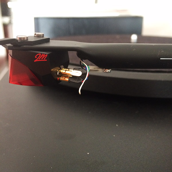
Recently tried to upgrade my cartridge from the stock Ortofon 5E to the Ortofon 2M Red.
When I was removing the old cartridge the wire connections were very tight. I managed to carefully remove them with a pair of tweezers, no apparent damage done to the connections.
I proceeded to mount, align, and adjust downforce. When everything seemed perfectly adjusted, I tried to put on a record... and nothing but a loud, low hum.
The turntable was working fine before. Admittingly a newbie, I am not sure how to start diagnosing this problem, a friend of mine with some experience setting up turntables was helping me set up the new cartridge, and was not able to figure it out what went wrong.
I'll be asking around to all audiophiles within my arm's reach, but have read some great forum threads here and thought I might ask for help from you.
Where did you purchase the table? If it is a brick and mortar audio shop, take it back and let them have a look. That after the sale service is a part of why you buy local rather than on line. They may not be able to fix the table, but they should at least look.
More than likely, and especially if the cartridge clips were tight on the pins, you've damaged one of the ground wires. It's rather easy to do but rather difficult to repair. And, problematically, to troubleshoot the issue, you must risk further damage to the wires and clips.
Alternately, you may have lost your ground connection by switching to the new cartridge. I can't remember the OM5 well enough (it's a design hung over from the 1980's and the days of P-Mount cartridges) to say whether it had a ground clip on the cartridge. I don't think it did but check anyway. It would be a small metal tab which attaches to one of the ground pins of the cartridge. I also don't know the Red. I do know it was never Ortofon's typical way to achieve a ground connection to use these clips but, with the Project, they might have made a concession to the design of the arm. So check both cartridges for a small metal clip that attaches to one of the cartridge pins.
Next you look at the ground leads from the table, if there are any. The table requires a solid ground connection from it to the receiver's phono pre amp. What you are hearing is 60Hz ground hum. It is a sure sign of a ground that has been "lifted" at some point. Double check you owner's manual for any instructions regarding a ground wire from the table itself. If one is provided, it should be obvious where to attach the cable at the table end since it will be a prominent screw point on the back of the table located close to the lead outs from the table. A single wire run to the ground lug of the receiver should then resolve your hum problem.
While both of the above will cause ground hum, neither by itself will result in loss of signal. So we probably need to look a bit more.
The first step now, of course, is to make sure you actually have the table connected to the correct inputs of your receiver. Sometimes it's easy to replace the RCA's in the wrong input when you're working with a lot of cables stuck in a very small space. Even more so if the receiver couldn't be pulled away from the wall or back of the shelf. So, just a quick look to ensure we should/could have signal flow.
Next, check the ground wires/clips at the cartridge for proper fit. Occasionally, you will bend a pin to the point it no longer fits snuggly on the cartridge pins. So make sure the cartridge clips are firmly attached to the cartridge pins. A visual check and a very light tug on the lead out wires from the arm should confirm sufficient contact to allow signal flow.
If that checks, you need to remove each clip from each pin and check for continuity to the lead out cables of the table (in other words, to the RCA plugs which attach to your receiver). This is where you risk further damage to the wiring by again pulling on the clips so be very careful here.
You will need a continuity checker or a (digital) Volt/Ohm meter (a (D)VOM). You are checking for signal flow from the clip end to the RCA end. Basically, this is accomplished on the DVOM by placing one probe tip on the clip and the other on the center pin and outer ground shell of the RCA with the meter set to "continuity". You have to disconnect the clips from the cartridge for a true reading. The internal "motor" of the cartridge can give false reading otherwise.
If this check shows a lack of continuity, then you'll have to track down where the break occurred. We'll hope you haven't broken a cable inside the arm itself as that would require a rewiring of the arm.
If none of these checks indicate a problem or if you get stuck somewhere along the line, contact Project. They should be able to talk you through the process and possibly recommend any other checks/repairs they have come across with the Ortofon Red on their arm.
When doing continuity for the cartridge wiring it is important to disconnect the cart. It is possible for the DVM to generate enough current to damage the cart which has VERY fine internal wire NOT capable of sustaining the current of a DVM in say��Diode Check, which will probably be the 200ohm switch position or right NEXT to it, one click 'down'. Even IF the wire is OK with the current, since the DVM uses DC for the test current, you will drive the armature of the cart FULLY one way or another. Bad for the suspension. Full output for a typical cartride is in the MILLIVOLT range.
I would remove ALL FOUR wires from the cart PRIOR to doing any continuity checks.
I have done some diagnostic testing, and It looks like I'll be rewiring my tonearm, as the cables run directly from the clips all the way trough the tonearm and to the terminal on the under the base of the table.
I know someone who will do it for me, but will need to find tonearm wires and clips. He is suggesting I purchase the wire with the clips already attached (see http://m.ebay.com/itm/360727381684?_mwBanner=1)
I am wondering what I should consider when choosing the cables. Is there an advantage to buying the wires with the clips already attached? I seem to find better options when looking for the parts separately.
I have otherwise been looking at Cardas cables. They offer all five wires (red white blue green black) with and optional shield/jacket around the wires in custom lengths.
Any idea where the cables are broken? Clips can be resoldered if you use care and a rather low wattage iron or a soldering station.
Which cables to buy depends a bit on your opinions regarding the value of wire in an audio system. Certainly, Project uses better than average cabling though, depending on your values regarding music playback, you might or might not notice a difference between wires. I would say contact Project and ask about buying wiring directly from them. Unless you care about wiring and how it might improve your system. It's unlikely the Project table came with tonearm wiring with the quality of the Cardas.
Are you familiar with the arguments for and against "audiophile" quality cables in a system?
My short answer would be to spend the money for the Cardas wiring. It's good quality and certainly can't degrade the quality of playback.
I'm not sure exactly where the cables are broken, however, I believe it is more than just one. I managed to get one channel working after wiggling the red wire, but the white cable is toast. I must have damaged a ground cable as well, because the low hum was still there.
I have read up on the audiophile cable battle, and think if I'm going to the trouble to rewire my tonearm, I mind as well put a decent set of cables through.
I do have a couple questions though- clips are made of several materials, I'm not sure what the kit Pro-ject clips were, but wonder what you recommend.
also, what about jackets and shields around the wires? I assume the benefit is that it would be easier to thread though the arm, or protect them in some way? would it add unwanted weight to the arm?... I'm not sure of the advantages to wrapping the wires.
I agree good quality cabling is a benefit to the music. I would not though get too hung up on clips and so forth.
First, let me say, though I spent 30 plus years selling high end audio and I am a firmly committed subjectivist when it comes to "tweaking" a sound system, I tend to either disagree or dismiss many of the claims for magic materials and construction methods made by the cable manufacturers. IMO they make a claim that is only partially true and leave out the vital bits which would lead a thinking buyer to pause for at least a moment.
In the case of clips and plugs and jacks and so on, every connector used in audio (with one known exception if it still exists) is using brass for its base metal. Brass adds strength and good durability. Brass though is very low on the scale of best metals for conductivity of an electrical signal. Next the brass is typically plated with other alloys such as tin and maybe even a bit of lead which provides the ability of the next layer to adhere to the clip. There might be some nickel in many connector's plating to provide a harder more durable final product. Once again tin and lead - those common materials used in the solder with which you will attach the tonearm lead out to the clip - are extremely low in conductivity as is nickel. Layering of materials in the plating process leads to dicontinuities in signal flow, less signal out from more signal in. If we really get picky, micro-distortions and phase shifts are occurring at this level.
Next comes the material being sold as a "gold" or "silver" connector. Any connector being sold as either material is basically false. The signal must first pass through several layers of lower conductivity materials to get to the microns thin plating of the surface material. That is, of course, after it has already made its way through the layer of solder - tin and lead - which separates the lead wire from the clip. How much signal loss is permitted by those lower conductivity metals makes the surface plating, IMO, pretty much icing on a two week old cake.
Gold, by itself, is resistant to oxidation which makes it a nice plating material since oxidation leads to signal loss and particularly at the cartridge clip level is difficult to remove. Gold by itself though does not withstand wear very well so the gold plating is mixed into an alloy with other materials for greater durability. The alloy lowers gold's conductivity which is near but not at the top of the conductivity scale. Silver has the highest conductivity of all the common metals but, like gold, is very soft and not well suited to a durable surface. When I build my own cables I use "pure silver" which is then placed in a protective cover. Silver does oxidize and rather rapidly which places a layer of material between the clip and the pin. It's generally agreed that silver oxide is less harmful to the signal flow than, say, copper oxide but it does exist and, in the overly paranoid world of the "audiophile", would cause extreme concern for some individuals at the micro-Volt level of cartridge output. To avoid excessive wear and oxidation of the silver plating, the silver is again made into an alloy which diminishes silver's inherent conductivity.
This makes the gold or silver plating virtually entirely cosmetic and, IMO, "bait" for the uninformed buyer. This is how virtually every "audiophile" connector used in a music system is constructed. And that only discusses the connectors and not the cabling itself.
Now that you know more than you ever thought you would need about cartridge clips, where are you? Buy whatever makes you feel best about your purchase. Audio is largely a series of trade offs, I give you one thing and I take away two things. In all the years I've been involved in audio, I have not found an exception to that rule. Perception is reality and, if you feel buying "X" is better, do so and don't second guess yourself.
While audio has mostly followed the idea of source first (nothing down stream can replace or repair a damaged signal coming from the source), small issues such as cartridge clips can keep some people up at night doing interminable searches for the single "best" item to try. You don't sound like the type who would do that but many are.
In many situations, signal cables do not require shielding from RFI (radio frequency interference). I run unshielded interconnects in my system and I can't determine a problem. We are though, living in a world with increasing amounts of RFI coming from numerous sources and your situation may not be my situation. And, even then, the extremely low level signals coming from a phono cartridge are the most susceptible in any system to picking up stray and unwanted RF signals.
It's almost always best to provide some type of shielding to phono leads. Running the cables inside a metal tone arm is the common form of shielding in this situation. Again, we could discuss the trade offs of such an arrangement but it is pretty much a game of arguing for the sake of argument. And, without meaning to say anything about the quality of your receiver, there is far more going on in the phono section of that component than needs to be considered with your tonearm wiring.
It's a bit of a PITA to rewire a tonearm but not all that difficult if you're careful. You normally can use the old cabling as your pull wire and, despite the risk you might damage the new wires, by going slowly and carefully, it's a job that can be done without a lot of fuss. Because the look of the job is somewhat like making a horse jump through the burning hoop for the first time, it does give a good deal of satisfaction when accomplished and also a great deal of drinking if you fail. A win win! At least temporarily if you fail. But we won't go there for now ...
Any alteration in tone arm mass will be minimal and small changes in balance can be countered with the weight on the back of the arm. I doubt you'll even notice the slightest difference in reality. I'm not sure what you mean by "wrapping". If the wires are inside the tonearm, nothing more is required and the short distance between in the tonearm and to the cartridge is insignificant.
Thank you again, this has been enormously helpful.
I do plan on doing the job myself, along with a couple of my friends who have some experience with delicate soldering. The biggest question holding me up is whether or not I should find some tonearm cable with the clips already attached, or do the tedious job of soldering the delicate wires myself, make sure I've got some heat shrink, and hope not to spend too much in the end.
I'll have to solder the wires anyway to the terminal, but that is much less of a job, and requires a less specific soldering tool. The problem is that I can't find any options that have the clips already attached that aren't either sketchy or expensive.
At this point, if I can get my hands on a decent soldering station, I plan on buying the clips separate and tackling the whole job.
I know basically what I'm doing, and have found some good instruction online from someone who has done the same in the past, but if there are any other good resources that you can point me to, I will gladly absorb more.
There are no heroes in tone arm rewiring. Have you contacted Project about a pre-assembled wiring harness? It may still be your best bet.
The two most important issues that arise when soldering clips to leadout wires are; 1) the temperature of the soldering iron and, 2) how to perform a soldering job which, at the least, requires three hands.
A soldering station answers the first though, for a one time job, this can get expensive. Even a 15 watt iron is a bit much for this job unless you are rather adept at soldering and can work quickly while also working accurately. Fortunately, with one exception, you do not risk permanently damaging a component with too much heat which is a very constant issue when soldering, say, integrated circuits in place. Don't put too much stress on yourself. Just remember you'll have wasted all your money if you screw this up.
A small heat sink clipped to the lead out just behind the solder joint is advisable. Otherwise the heat from the iron is likely to melt some insulation while you're getting the conductor up to a proper temperature. In a pinch, if you have the extra room on the lead out, a small alligator clip can work as a heat sink though there are devices sold just for this purpose. But a heat sink is highly recommended when working on such delicate pieces. The alligator clips on the next device are OK but a secondary is preferable for tone arm leads.
If you've done a good job soldering the lead to the clip and you've not boogered up the insulation, I'd forgo the shrink wrap. It's not really necessary for this job and you'll have a hard time finding wrap for the size of the joint where you have a wide clip base and a small lead out wire. Also, it's one more function where you risk making a mess of the joint by using heat where it's not really needed. I'd definitely skip this step if I were doing this job. It's more cosmetic than functional on this joint. If you don't spend about $50 for a low/adjustable temperature heat gun, you'll need to use a flame to get a proper fit on the shrink wrap which will discolor the wrap anyway. Most hairdriers won't work well for this job.
The second issue is taken care of by a "helping hand"/"extra hands" clamp system. Something more or less like this; http://www.radioshack.com/carson-gn-88-helpinghands-magnifier/55057307.html#star t=88&sz=12 There are several versions of helping hands out there, this is one of the least expensive now, I guess. I bought mine when they were about $7. Doesn't look like those days are anywhere to be found. Shops that sell electronics supplies are likely to have a few options too. I use Allied Electronics out of FT Worth for a lot of small pieces and minimal cost orders.
Basically, you just need extra hands that are steady and will hold the pieces together for those critical moments - seconds actually - after the soldering tip has been removed from the joint and the solder cools to a solid. If you try this by hand, there's a good chance you'll move one of the parts which could lead to a "cold solder joint" which is not what you want. Cold solders are susceptible to signal loss and can even turn into small diodes which will pick up stray RFI.
Unless you buy a wiring harness with pre-stripped and tinned ends at the clip you'll also need a stripping tool that can accommodate the very thin lead outs of the tone arm. Most tone arm leads are in the range of a 26 AWG or smaller and, if you try stripping the dielectric from that cable with a tool best suited to 10-18 AWG cables, you'll likely mess up the lead out.
The best solder is no solder. The problem with no solder is oxidation in this case. Oxidation which occurs between the parts is rather like another cold solder joint, it will eventually cause problems unless you seal the joint from the open air. And, of course, if you ever pull on the joint to, say, change cartridges again, you can tear the joint apart and you'll have to start over. Therefore, most tone arm lead outs are soldered rather than crimped.
Solder is primarily tin and lead which we've already discussed. They are impediments to good signal flow. So you want to first make sure you have a solid connection between the lead outs and the clip. It's preferable to "wrap" the lead out over the edge of the clip to ensure a tight surface to surface contact before solder is applied but this is a little OCD and can cause problems if you ever have to re-do the connection. "Re-do" as in you've made a bit of a mess with your first attempt.This is a small joint you're assembling and small isn't always where you want to be for your first try. A simple 90 degree bend in the lead to "latch" the wire to the clip (most clips have a re-drilled hole for the lead out) will be sufficient. Once you apply solder to a "wrapped" joint, you'll never get the pieces apart and they are then simply discarded and new parts with stripped back leads are used. The next best solution is to add the one bend, set up your helping hands to maintain consistent placement of the two parts and then carefully use only the amount of heat and solder that makes the joint solid without using too little or too much heat and solder to make the joint less effective. Make sure you know what a good, proper, finalized solder joint should look like before you begin. How to solder instructions are on the web. Then just practice with some scrap cabling to achieve consistently good results with your work.
Even "silver solder" is usually no more than 4% silver. Just enough to give it a name. Radio Shack sells - or did sell - a small, fairly inexpensive package of 4% silver solder which should be sufficient for your job. Otherwise, if you want to get better, you'll need something like the long time standard for diy builders, Wonder Solder; http://www.thecableco.com/Product/Wonder-Solder--Lead-Based-
With lower impurities and a (very slightly) lower melting temperature Wonder Solder is the preferred solder for high end audio. First though, whether you'll notice a difference between it and a basic silver solder is difficult to prove. The quality of a solder joint is really far more important than the solder itself. The iron will usually add a sufficient amount of crud to the joint that impurities in the solder become secondary. So have a clean tip on the iron with just enough solder coating it to ease the job along. Second, if you get a bit OCD about this job, you'll have spent enough money that it would have been more cost effective to simply trade in your non-working table for a far more expensive and probably higher quality turntable. For the diy hobbyist, some of this stuff will get more than one use. For someone repairing their tone arm, this may be the last time you ever use the stuff unless you change your attitude toward audio. Therefore, invest appropriately. Small changes can make big differences in your system but, once again, keep in mind this is plugging into a Yamaha receiver and not a $5k Audio Research tubed pre amplifier.
Having all the tools required for completion of the job in one sitting and already in place plus getting a nice clear, open space for the job makes everything go smoother and with less frustrations. If you are going to do the soldering yourself, practice on several scrap pieces before you attack the real thing. Learn how to get your materials to their proper temperatures before you lightly "tin" the ends. Make sure you know how to apply heat to the joint and what the joint should look like when you're finished. Too much solder on the joint is just as bad as too little solder. Melting the insulation off the end of the lead out isn't what you want though at times must be accepted as reality. Just try to minimize the mistakes. Soldering is a job you can teach an eight year old but a lot of adults so totally "F" it up, it's unbelievable. Practicing on various small parts is best before you start on your arm.
I assume it does not need to be said but do not use your cartridge to hold the clips while you are soldering. You'll also then need to get the pin to temperature which will be enough to cause the internal solder joint to come loose. Then you'll really have problems.
The task seems daunting, especially with the 33awg tonearm cable, which I don't even have the tool to strip. finding someone experienced is maybe my best bet, but my instincts/personality is certainly a "make the most out of a situation" which in this case, is teaching myself some skills, however, an investment in a good set-up to complete this task properly is certainly an investment, both time and money, and a question of personal interests... still on the fence.
I've contacted Pro-ject and haven't heard yet, I'm sure they will be able to supply me the cables, it may be a matter of cost.
In any case, a soldering iron is a useful tool, definitely something I see myself using in the future. On the other hand, this task may be better left to a confidant one.
I hope I haven't made this appear near impossible. It's not, just tedious and, if this is your first time working with small parts, it can certainly look difficult. Actually, frying an egg is about the same difficulty as soldering a cartridge clip. Except the egg is much larger.
When you first assemble all the required tools it can begin to add up. I'd say the expense is more of an impediment to doing this yourself than the actual soldering job. You can learn how to create a good, functional solder joint in less than an hour and probably even less than that. And the world will not end if you have a bit less than perfection in the final joint.
Here's your stripper; http://www.alliedelec.com/ideal-industries-45-125/70225334/
It will very likely be $20 spent for a one time use. It all adds up.
I have contacted them, they sent me to the Needle Doctor, which is where I have already purchased some Cardas cables and clips. I've called them, they will sell me a new tonearm, but not the wire and clips only. At that point I should really just get a better table. They did advise for me to re-solder the wires to a new set of clips, if I have to shorten one of them, they told me it won't make a noticeable difference in resistance, as the cable is about 2' long.
They also recommended that I use the iron to melt the jacket of the wires instead of stripping them.
A question about the heat shrink- without it, does it potentially cause any interference issues? I trust it would not, but it seems to be a pretty standard way of protecting the joint.
also, I can find soldering stations that have a range of 5-40 watts for a reasonable price. I'll obviously figure out quickly the proper heat setting, but want to make sure that adjustable range will be suitable for the job.
Sell you a new arm?! Well, that's big of them! That might be an answer if you got cash back for the old arm. But, obviously, what are you going to do with a non-functioning arm? It makes for a lousy spaghetti strainer.
There are independent dealers who still take trades. Maybe you could work out a deal with one of those dealers. They will deal over the phone or on line. Or you could put your old arm on sale on line. Of course, an arm that needs repair is rather like the car that has to be towed to the trade in. You'd have to make up your own mind which is the best move for you. How much will you spend to buy all the gear needed for the repair? If you loose that much plus the value of your time, then I'd say consider that as a possibility.
In the logic of tables, the table is more important than the arm. If the table is allowing signal loss or distortion, a better arm will only show that to be a fact. The cartridge is the least important of the system. It's not that you can't upgrade an arm on an existing table. Lots of people do so. And a lot of tables being sold aren't truly that different other than for the arm. The Project arm is about the same as the Rega arm and they have several models with very little difference between them. Modifications to existing arms on both tables are available.
Have you looked on line for anyone who does mods to the Project arm? They would take your existing arm and do the rewire and probably also tweak a few bits and parts to make for a better arm while returning your old arm to you or making an exchange where you got credit for the old arm. That might be a good idea at this point as the cost of tools for the diy begins to add up.
Are there any local audio clubs in your area? You might find someone there willing to take on the job and their cost might still be less than buying all the equipment. Maybe a tech school/high school where you could pay for someone with the equipment to do the job? Go to the local music shop where they sell guitars and amps. If they sell to DJ's, they should have someone willing to take on the project.
Heat shrink is good for certain applications. If I'm soldering up some plugs that will have closely fitting parts or will be handled more often, then I might use some shrink wrap. For jobs like attaching leads to the clips of a loudspeaker driver, I don't bother. There are essentially two ways to make a joint in cables, plugs, etc. You can either solder them and that will be sufficient though you might want to add some shrink wrap if the joint will be handled a lot. Or you can make what's termed a "gas tight" crimp. A gas tight crimp won't allow for oxidation which is your enemy in connecting parts. Shrink wrap can substitute for or supplement to a crimp. But it is difficult to get a shrink wrap that is effective when you are using it on two parts of greatly disparate dimensions. There it becomes almost completely cosmetic.
You can use a hot iron to melt the insulation. Works better when the dielectric is PVC and not Teflon. I don't care to do it that way but you can do it that way.
No tech today would be without a soldering station. They're working with small, easily damaged parts all day. Too much heat and they're going to get another part that they'll have to pay for if they screw up enough of them. Again, the question becomes cost effectiveness. You can do this job without a lot of worry by using a fifteen watt iron and working rather efficiently and somewhat quickly. I'd still tell you to do some practice before you went at the clips either way. And a heat sink of some sort on the lead out would be best.
If you know the conductor is broken at a specif point, yes, you could snip that part out or simply add an extension of a few inches. You'll still be doing some soldering. It won't matter to the sound quality if you do a good job. It might matter to someone who you are trying to sell the table to later.
I'm an experienced solder guy and would not like to do this job, though I suspect I could I repaired a friends HEADPHONES which use wire easily as fine as that in a tonearm. It was a BEAR. But I was lucky and it was FINE. Just as bad, or nearly so, was the board level repair I did for the neighbor who had a power adaptor plug break on a small handheld device. THAT had something like 8 solder connections. Using solder wick and a magnifier AND some 'helping hands' type devices, I again got lucky and it WORKED after the part was replaced. I hate cheap circuit boards.