This may be slightly off-topic but I didn't see where else this could be applicable...
Helping replace speakers in a charitable organizations 40x60 ft hall. Using a TOA 120W amp with 4,8 ohm outputs, and 25v,70v outputs.
Goal- Mostly PA-type usage for a local Bingo run out of the hall.
Ignorance and extreme price consciousness ead to the following purchase decisions: Speakers from MCM electronics part No 555-6390; 4 speakers, •Power capacity: 30W/60W RMS/peak •Frequency response: 40Hz ~ 20KHz •Nominal impedance: 8 ohm •Magnet weight: 17.7 oz. •Voice coil diameter (woofer): 1 1/4" •Sensitivity: 86dB (W/M)
Along with 4 audio transformers MCM part 555-7125 30W •Secondary impedance: 8ohm •Primary taps: 5W, 10W, 15W, 20W and 30W
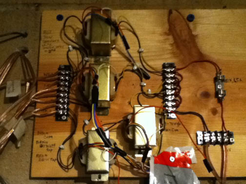
Built an interface board (photo below) to interface transformers wih speakers. Essentially, running four separate speaker wires (16Ga) from speaker to the interface board. Doing this for future flexibility (i.e., is go away from 70v system, wanted to have speaker wire that could do OK with max 75 Ft run between amp and speaker without needing to rerun speakers cables. Plus, don't need to account for 70v speaker wiring in ceiling... More info in nex post for those that dare to continue (and give much appreciated input)...
So, the 4 audio transformers are wired in parallel with the 70v Amp o/p. 30w output from each transformer is wired to one 30W speaker. Shortest run between transformer o/p is 25Ft. Longest run is 75 Ft.
Before this setup, a single 30W speaker was being driven by this amp. at an amp gain of 7, crude measurement techniques using a Db sound meter ($49 from Radio Shack) at 6Ft. measured in the 80dB range from existing speaker wired to 8ohm o/p. I/p was not a test signal, but rather a crude attempt in speaking through a microphone into amp i/p trying to keep voice constant level. Crude I know, but best I could do... Going through audio transformer (30W secondary tap) to single 30W speaker, I need to crank amp to almost 10 to get in the 80dB output, and there is significant distortion. Some testing results through my crude testing in the next post. Ultimately, I'm trying to get more sound through the newly purchased 30W speakers, using this amp.
So, I'm getting either distortion or clipping from the above setup of 4 speakers wired through 4 70v audio transformers, froma 120W amp.
I tried spome testing to see if I could limit/rule out causes of the distortion/clipping (i.e., is my distort/clipping caused from cheap audio transformers, using 16 ga speaker wire in long runs, using 16 ga speaker wire in long runs from the audio transformers). My goal was to get approx 80db o/p from each of my 4 speakers mounted in the 40x 60 hall.
Here is a summary of my understanding of my testing results (details of testing and crude results listed below): It seems that overdriving the amp is not the cause of distortion as my results for 1 speaker o/p were similar for distortion as for 3 speakers hooked to amp (albiet 3 speakers hooked to amp caused a significantly rediced decible level o/p at each speaker).
Driving the transformer through 20W secondary still caused distortion.
Driving the speaker with 5 ft. distance between transformer secondary and speaker still caused distortion.
For both the original and a test speaker, removal of the transformer from the circuit and driving directly from the 8 ohm o/p removed distortion completly, and gave similar 'loudness' results through through different speaker wire size and length runs.
I'm really trying to determine what the cause of the distortion (clipping?) is so I can get more sound out of the 4 speakers- shooting for an 80dB measurement on my crude measurement technique from each speaker. Do I need higher quality transformers? Different gauge speaker wire from my speaker runs? Mount the transformers at the speakers (trying to avoid this but will do it if necessary)? I'm OK with some losses, through inefficiancy of 70v transformers (and possibly from 75 ft run on the one 16ga speaker wire run?), just trying to get more volume/sound out of the system (80 dB at eash speaker measured from 6ft).
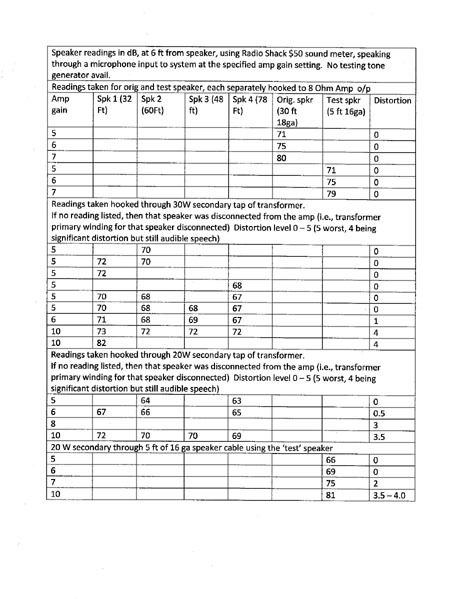
Here are some testing results for sound o/p for 16Ga speaker wire with following runs between trans. secondary and speaker: Spk 1 = 32 Ft. run; Spk 2= 60ft run;Spk 3 = 48 Ft. run; Spk 4 = 78 Ft. run; Orig Spk. = 30W 8Ohm, through 32 Ft. 18 Ga. wire;
I did vary the number of speakers hooked to the circuit to see if I was over driving the amp. So, the level of speakers recorded is the number of speakers hooked to the amp at that time (I disconnected speakers by disconnecting the primary transformer winding from the amp o/p.
All readings for the orig, speaker was taken with 30 w Speaker hooked to the 8ohm amp o/p. Readings for Spks 1-4 taked through their respective audio transformer hooked through the 70v amp o/p
Distortion (clipping) measured on a 1-5 scale, with 5 being worse (4 being very noticle but still audible speech being heard.
Results as attached .jpg table
I did try hooking a single speaker through 5 ft 16ga speaker wire from transformer o/p and still received similar distortion/clipping as through longer speaker wire runs.
I tried hooking a single 'test' speaker through 5 ft. speaker wire directly to 8Ohm o/p of amp, and measured sound at 6 ft. Gain 5, 71 dB, 0 distort. Gain 6, 75 dB, 0 distort Gain 7, 75 db, 0 distort.
I took some 'Baseline'readings from original speaker hooked directly to 8ohm amp o/p, sound measured 6 ft from speaker Gain 5, 71 dB, 0 distort Gain 6, 75 dB, 0 distort Gain 7, 80 dB, 0 distort.
As mentioned above, I'm trying to guess with very limited experience in this area my distortion reasons. IT seems from the above that my distortion is from the audio transformers. I'd like to use them, rather than use a 2 in series, 2 in parallel config for 8ohm amp-output if possible. Essentially, I'm trying to use the 70v o/p, to get in the 80db range with no distortion.
Any thoughts are appreciated as to the distortion (clipping?) causes of this system, and whether it is salvageable to get my desired 80dB per speaker...
It's been a while since I've dealt with 70 V lines but my first guess would be your placement of the transformers. Transformers have an electromagnetic field which surrounds them and there will likely be interference between two or more transformers when each unit is placed in a similar direction to another nearby transformer. Your placement of the transformers on the board would be the least desirable choice IMO. Look at how multiple transformers - or coils/inductors - are placed on a speaker crossover board and that should give an indication of how to align the transformers. Or, put the transformer at the speaker itself and run from the 70V output of the amp to the transformer.
You might also consult the owner's manual or contact the amp manufacturer/distributor/retailer to make sure there are no switches or internal busses which need to be in place to make the 70v outputs operational. Given the 4/8 Ohm output, there is likely a current limiting switch in the amp or some other transformer which might need to be dealt with.
Finally, double check your connections to make sure you've not mixed up the 70 V and 25 V lines/taps.
Other than that, I don't understand the use of 70V lines for this application. IMO you're wasting money having the transformers and, if the system operates without distortion through a direct connection of amp to speakers, that's the way to go. Save the 70V lines for the next time you wire a five story department store's PA system.
What's your objection to the parallel/series connection?
Jan, first thanks for responding to such a long (and convoluted) post. I hadn't even considered distortion introduced due to the proximity of the transformers to each other. I *might* have ruled that out, however. I disconnected three of the transformers from the 70v o/p, and used the fourth (albiet still mounted in proximity to the other three) hooked through a 5ft speaker wire to the speaker. In that situation, I was trying to rule out distance between the speaker and transformer as a cause of the distortion. In that case, the distortion was about the same as with all transformers operating. There is a possibility that the single transformer operating could induce a current in the neighboring (non-operating) transformer, which in turn could induce a distortion back in the first transformer. I suspect it would be much much much smaller than if all four transformers were operating at the smae time... more to your series/parallel combo in the next reply.
Good points about double checking connections. I did, and they were correct (i.e., hooked to the 70 and not 25 v o/p). And I do know that the 70v o/p is live all the time, and actually was using that o/p for my testing.
I'm actually rethinking an earlier decision against the series/parallel wiring combo of the speakers. Originally I thought I would risk blowing the 30W speakers hooking the series/parallel (8 ohm equiv.) combo to the 120W amp. I believe I'm in error however...
The equivalent impediance of the series/parallel 4-speaker combination would be 8ohms. This would seem to deliver just shy of 4A at around 30v. Each 2-speaker series leg would receive 2A. Thus, each speaker would receive P=I*I*R , which would be 4*8 so 30W... So, really, by hooking 4 30W speakers in a series/parallel combination at the 8ohm o/p of a 120W amp should not give a great chance of blowing the speakers unless someone cranks the amp pretty high (i.e. 9 or 10?)... Please feel free to correct me if my reasoning is incorrect...
So, is there any reason I wouldn't want to take the transformers out of the circuit, and use a 2-speaker in series, 2-speaker in series, and place those in parallel to get 8Ohm equiv o/p impedence. Hook that to the 8Ohm amp o/p. Just take the 70v out of the equation. Since everything is run to my interface board, I could do the parallel, series combination right at my interface board.
Now my 16ga speaker wire runs coming the interface board vary from 30Ft. to 75Ft. Now, doing this (i.e., wiring two sets of the speakers in series, and paralleling that combination) would increase each of the two series wiring runs to about 210ft using 16 ga wire (this is becasue I wired everything back to the common interface board). However, there would only be 2A traveling through these speaker wire runs. I'm betting that I could get away with 2A running through 210Ft of 16ga wire without problem.
Now, another concern would be should a speaker be blown (or otherwise inoperable), it would change the equivalent impedance of the combination and damage the amp. As you mentioned, I do believe that the amp is protected. In this config., since the current would be 3.9A max, I could even place a 4A fuse in my interface board (at the point where the 8Ohm amp output enters my interface board) to help protect the amp incase the circuit impedence changes becasue of failed speakers...
Does my rationale seem correct (esp. regarding little concern about 2A through 210Ft of 16ga wire)? Maybe I'll just go the series/parallel wiring combo in my circumstance since I'm only dealing with 4 speakers...
The best location for the 70V transformers, if you want to use them, is at the speaker.
It's not cheap if you want quality but the best option for your set up, IMO, would be a speaker selector with autoformers. http://www.crutchfield.com/S-H151UPuZA8r/p_543SDB21/Russound-SDB-2-1.html
But even that would seem to be a bit of overkill for your application. The autoformers will ensure the amp sees a constant impedance no matter how many speaker systems you connect. The only limitation would be the amount of power available, which you seem to have in abundance. However, as I said, this looks as though it is still way more than you should need.
I will confess to being a bit lost in all of your computations. IMO you're overthinking this.
You have four speakers, right? One two channel amp, right? The amp has a four Ohm output. Which suggests the amp can drive that load without problems. More than likely, unless the amp uses transformers at its 4/8 Ohm outputs (which would be unlikely), the amp produce as much as twice its rated wattage into a four Ohm load (though admittedly peak current will be limited, a non-problem in this application). Particularly when you say this is for bingo, you should not run out of available power.
Power requirements are minimal for vocal range reproduction. Put music through the system and you should still be fine ... unless you allow mentally impaired adolescent chimpanzees near your system without adult supervision.
I'm unclear how your speaker lines went from 75 foot max to 250 foot runs. Why not just run the two speakers per side in parallel and drop the nominal impedance down to about four Ohms. Run lines from the amp to the first speaker and from that speaker to the next. Shouldn't that minimize your speaker runs?
The amp should be fine with this set up if you make your connections to the four Ohm outputs. Even if you make the connection to the eight Ohm outputs, you'll still have enough power to make the system work despite the slight issues of impedance mismatch. Speaker systems aren't just one overall impedance so there's even the chance the amp might be happier run from the eight Ohm output with a parallel connection of the speakers. It's a bit of a non-issue as you have plenty of power to go around. I don't know since I don't know these speakers. But you shouldn't endanger the amp if you just make a straight forward connection to the four Ohm outputs. There's a small possibility the actual impedance of the combined load would drop somewhat below four Ohms at some frequency but that issue too would be minimal and only a concern if you try to do loud music through the system.
For bingo you should be fine.
So there is the question of who will be allowed access to the volume control. If you're relatively sure no idiot will be allowed within fifty feet of the system, there's nothing to worry about.
If you are concerned about who might have an opportunity to run up the volume with bass heavy music, put a fuse in line with the tweeters only. Fuses are sort of the last ditch effort to foil any attempt to get more volume from the system than it can supply. At a four Ohm load the amp will likely shut down before the speakers are damaged which would make a tweeter fuse less useful and more work than is probably needed. But tweeters blow from not enough power. In other words, when the amp begins to clip. If you are the nervous type, place a small amperage, fast blow fuse in line with the tweeters. Don't expect it to make the system bullet proof. The dynamic nature of music means there is no constant amount of amperage running into a speaker. This makes an overall fuse for "the speaker" less able to actually protect the system. A smaller fuse located at the tweeter where clipping distortion is near constant will probably protect the system from an over zealous music lover yet would never be blown when voice only is running through the system.
It should be fairly difficult to damage the woofers unless someone does something truly idiotic. I really wouldn't even bother with the tweeter fuse myself but, if you have concerns with who might have access to the system, this would, IMO, be your best bet. Music will start to sound bad when the tweeters aren't working and anyone with any sense should then turn down the volume. You know what the situation is with this system, so you decide.
But scrap all the other things you've calculated, they don't really matter IMO. You're setting up a system for bingo. Your amp can run at a four Ohm load. Your two eight Ohm nominal speakers will be four Ohms nominal when run in parallel. Power requirements should be minimal though the amp should be producing substantial amounts of power when faced with a four Ohm load.
I'm assuming the speakers will all be playing at any one time and there is no reason to shut down any set. If you need to run just two speakers - front or rear, not left or right - at any time, buy a small speaker selector switch box with impedance protection. This allows you to place a fairly large wattage power resistor in line with the load so the amp should be fine with the total load. The loss through the resistor shouldn't be an issue with the amount of power you have available.
You could also, of course, contact TOA or, really, most any sound reinforcement company in your area for further advice. The information you need shouldn't even require a site survey.
Keep it simple and run as short a cable run as possible.
Thankyou Jan. The amp is a single channel Amp I believe, and there is an external switch that changes the 8ohm to a 4ohm o/p (so perhaps an internal transformer?).
I didn't really expain how the spkr runs changed. For parallel, the longest would just be 75ft. as they all come back to the interface board. For series connection, the run doubles (i.e., there and back) + a round-trip run to another speaker. The run is actually closer to 210 and I padded it a bit for some wiggle room. So, I just need to make sure that the 16ga speaker wire can handle the max current (I roughly calculated at 2A, but I think it'll be closer to 1.9A)for each series speaker run. I'm OK with numbers, and just want to make sure that what I set up can be handled by the various components/wires of the system. 18ga speaker wore probably wouldn't work for those lengths. If the amp was two channel, I like the option of just running two parallel speakers two each 4ohm channels. But with a single channel o/p, I'm not sure how to get 4ohm or 8ohm where each speaker gets 30W power except for doing the series/parallel connection.
I'm going to forget the transformers, mainly because the more I read, the more I'm convinced that cheap transformers are the source of the distortion (and even more expensive won't eliminate it). Rather than spend $40 or more per transformer for better transformers, I can just use a series/parallel connection for the speakers (to get 8ohms) to be driven by the single 8 ohm o/p channel. A pretty straight forward solution (I mis-thought it out earlier that the combination would only handle 30W- the calculations I did showed me that I should actually get 30W at each speaker with that series/parallel wiring).
"unless you allow mentally impaired adolescent chimpanzees near your system without adult supervision" Well,there's always a couple in every crowd and hopefully they won't really have access. But, the speakers are cheap ceiling mount types, and we bought some extra for that contigency. I'll just throw a 4 amp fuse in line, and it should protect the speakers (or a least the amp). As you mentioned, for Bingo it should be fine (and evn the rare for-music use). And no real separate woofers/tweeters. Just cheap single-function speakers (a kind-of tweeter built in, but not separably fusable).
The big thing about my calculations (assuming that they are good estimates) is that the wire can handle the amperage, and that the confirmation that the speakers will actually each get up to 30W max power so I know it will be 'mostly' blow-resistant with a 120W amp.
"The amp is a single channel Amp I believe, and there is an external switch that changes the 8ohm to a 4ohm o/p (so perhaps an internal transformer?)."
Well, do check. That would make a difference in your connections. Not many mono amps out there but it could be. Do you have a model number?
Impedance switches are common nowdays on lower priced amps. There's no internal transformer in most cases since that would add to the expense of the amp. And a transformer would simply have multiple taps and no switch.
Switches add a sort of protection circuit to the output which serves to limit Amperage. For more critical listening to music, this circuit is undesirable since the ever changing impedance curve of most speakers combined with the dynamic nature of music makes current delivery a bit of an issue. There's nothing to worry about in your application. Current will not reach full peak delivery which can keep the amp from overheating when the switch is in the four Ohm position. For vocal reproduction, nothing should sound one bit different with the switch in the four or eight Ohm position.
So, first, find out what sort of amp you are working with.
If you have a mono amp and four speakers, you get creative. Run each pair of speakers per side in series. This will give you a nominal 16 Ohm load per side/pair. Combine the two sides at the amp - or at a terminal strip - to create a parallel connection at that point. Do you understand how to make this connection?
Run from the eight Ohm outputs of the amp with the impedance switch in the eight Ohm position. Two eight Ohm loads in parallel will be four Ohms at the amp. It will be fine and it will produce higher overall wattage. If it begins to run overly warm with this set up, move the switch to the four Ohm setting and check again.
Single driver ceiling speakers don't wander in impedance and you'll have an essentially straight forward load on the amp. This will give you only one long run of cable on one leg - the return to the amp from the second speaker; http://www.regiscoyne.com/tech/spk_cab_wiring/ No concerns about power drop off over length. Just use decent cable.
That should minimize your cable runs again. And your system will be set up in a way that will shut down both speakers if one speaker fails. Therefore, any abuse will quickly show up as bad sound and the system shouldn't be damaged. Speakers are pretty tough when there's no crossover to a separate tweeter. Clipping distortion occurs when the amp runs out of power and this is what destroys most speakers. Without a discrete tweeter, it's very hard to blow up speakers unless you really try. Of course, nothing is impossible.
Your four Amp fuse is probably too high. Best way to set the fuse rating is to buy a group of fuses at various amperages and test them individually with some bass heavy music. When the fuse blows just before distortion kicks in, go back one level and use that as your go to fuse rating. Check for adequate volume levels with your vocals. Then throw the others away so no one can stick a four Amp fuse where a 1.5 was installed. And buy a supply of spare fuses in the correct rating.
Don't worry about power delivery to each speaker. It will be fine. A series connection means the first speaker receives the highest current and the second speaker slightly less but, with vocals only, this just shouldn't matter. Even with music this is acceptable since there's no critical listening going on.
Prudence would suggest 16 AWG cable for a 75' run. The losses from inadequate gauge are relatively even across the board. They aren't going to roll off the highs or lows, just a gentle drop in power delivery as length increases. Most people would be hard pressed to actually notice the loss unless they were told it was present.
Whichever speaker connection you decide on, lay it out on paper so someone looking to get the system up and running when you're not around will have an easier way to go.
I do believe is is single channel, 120W. Your speaker config confirmed my thoughts, and what I was planning (since deciding to forego the transformers and 70v aspect).
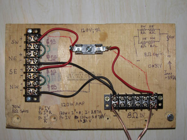
I do understand how to make that series parallel connection- thanks for checking though... I believe that the two 16ohm series legs in parallel would yield an 8ohm equivalent circuit (which I can connect to the 8ohm amp output). I've attached a photo of the interface board I made today for the series/parallel connection, with an i/p from the amp. It includes the claculations I made to determine the max voltage and Max current (looks like 3.9A at max amp gain) I should see from the amp (and into the speaker wire). It also includes a basic diagram for those that come after me. Becasue of the parallel connections, the amperage should come pretty close to splitting between the parallel legs, so max current through each parallel leg would be (by my calculations) 1.95A. Power max at each speaker shoud thus be I^2*R which would be 30W. (Though the amp should never be turned up to max gain). Thus, even at amp gains of 8 or 9, the system should be fine. Should something weird happen, and a short occur, the 4A fuse should protect the amp externally (and there is internal fused protection in the amp as well).
From what I've seen, I agree with the 16ga speaker wire. That should provide less than 5 percent loss for 2A current over a 210Ft run (i.e., series connection between closest and furthest speaker of 75 ft there and 75 ft back from longest run, and 30ft there and 30ft back for shortest run- and similar length for the two internediate speakers if the second series connection) through each parallel leg having the speakers connected in series). I'll put an ammeter into the circuit to confirm max current when I'm testing the circuit/speaker config.- I'm thinking I'll hafta read DC amps as it may be fluctuating, but will always be in the same direction...
It's good to hear that the sound quality should be OK, even if we play some music through the system (though again, we're gearing towards PA/voice).
Oh, the green wire at my terminal strip makes the two series legs, and the red/black wires hook them in parallel. The speakers would be hooked at each of the four i/ps to the left of the diagram (and the compass directions indicate which corner of the hall). I see the right edge was cut-off from this photo. Oh well...
Yes, sorry, brain phart on my part. The parallel load on the amp will be a nominal 8 ohms.
This looks to be the amp; http://www.toa-products.com/international/download/manual/p906mk2_mt1e.pdf
That's an odd output configuration IMO. Transformer coupled for 8 Ohms (and 25/70 Volts) and direct coupled for 4 Ohm loads. I'd try the transformer coupled 8 Ohm output first, it should work fine. Make sure the switch is in the correct position.
Hooked up the new interface board (8 ohm system- avoiding 70v) and was surprised at all the smoke and flame that 30v at 4A could make. Just joking!
The system worked well! I placed the ammeter in the circuit, and at the amp gain of about 7, the speakers were drawing around 2.25 - 2.5 Amps... The sound was loud and clear. And, readings from my inexpensive sound/dB meter gave a reading of around 80dB. The amp could still be turned up, but I'm certain that this will be sufficient.