Impedence clarification
|
Silver Member Username: James_the_godLancaster, Lancashire England Post Number: 846 Registered: Jan-05 | Hi. I hope everyone here is well. I'm considering purchasing some Dali Suite 2.8 floorstanders. However, they are rated at a nominal impedence of 4 ohms. The spec sheets says the minimum impedence is 3.5. Now whether this means too much or not is where you may be able to shed some light. My concern is whether a normal integrated amplifier would be alright driving these speakers or something else is needed. (I can't afford new speakers AND amp). For those that remember, I'm still using the Marantz 1060 integrated amp, made in 1973. Many Thanks JJ |
|
Silver Member Username: HawkbillyNova Scotia Canada Post Number: 895 Registered: Jul-07 | I think these speakers are of the low impedence but relatively high efficiency persuasion. Their efficiency rating (90db) would lead you to believe they are an easy load, but I would think they would require an amp capable of relatively high current. Without know the phase and impedence plots it's hard to say with certainty. The Marantz 1060 looks like it's 30 watts RMS, which isn't a lot, but some older amps had pretty beefy power supplies.....not sure if that's the case here though. Someone else will likely be along who knows your amp better than I do who'll be better able to advise. |
|
Platinum Member Username: ArtkAlbany, Oregon USA Post Number: 12441 Registered: Feb-05 | I used to have that 1060, it's swinging out of it's league with the Dali's. I'd keep it "easy to drive" with that amp. Not a bad sounding piece, I used it with Altecs. |
|
Silver Member Username: KbearCanada Post Number: 590 Registered: Dec-06 | From what I've read over time, 4 ohms is kind of the magic number. Any dips below that can tax an amp. If there are none of these dips then most amps should have no problem. I'm sure it's not that simple though. I think another factor is what the impedance plot looks like...how steep are some of the lines. As Chris said, I think you have to look at both sensitivity and the impedance plot. An easy load (impedance-wise) with a low sensitivity...I think that would mean most amps can drive the speakers but you need a lot of power (watts) to drive them to loud volumes. The opposite (low impedance, high sensitivity) suggests that you don't need a lot of watts to attain high volume but you'll need an amp that can generate lots of current in order to overcome the load. In short, the sensitivity is only a measure of how loud the speaker will go (given a certain number of watts), while impedance is how hard the amp needs to work to actually drive the speakers successfully. Those frequency ranges with low impedance will require extra current. It won't be needed all the time, but your amp better be able to provide it when required. This is just my impression given all I've read over time, so someone please correct me if I am wrong. |
|
Platinum Member Username: Jan_b_vigneDallas, TX Post Number: 14757 Registered: May-04 | . http://www.symphonysound.com/articles/tubefriendly.html . |
|
Silver Member Username: KbearCanada Post Number: 591 Registered: Dec-06 | That's a great article, Jan. I have a much better understanding of impedance graphs now. One thing I wish they would have elaborated on a little is phase angles and the terms "capacitance" and "inductance". I've done some searches in the past on phase as it relates to speakers but wasn't able to turn up anything the quality of the link you posted. I'm still not entirely sure what "phase" really is, and when people say "in phase" and "out of phase". One thing I've noticed in Stereophile's speaker measurements, they often highlight sections of the impedance curve that are not smooth. I think this signifies resonance issues in the speaker at a certain frequency, and from what I can tell it often exacerbates the load put on the amp. Just from what I've gleaned from Stereophile's comments. This all shows how tricky it is matching an amp to a speaker. It's tough to come up with ideal matches if you don't have a good understanding of what's involved. Have I come up with poor matches before? I'm sure I have. I bet most people have. When you consider just how important the impedance and phase angles of a speaker are to the amp chosen to power it, I don't want to say speaker companies should be forced to publish these graphs, but yeah, they should have to. I've searched for measurements of many speakers over the years and those searches have turned up empty. Unless there is a Stereophile or Soundstage! review, you are probably S.O.L. |
|
Platinum Member Username: Jan_b_vigneDallas, TX Post Number: 14758 Registered: May-04 | . Impedance squiggles due to cabinet resonances are typically rather minor things that really only matter to someone like JA. Cabinet resonances do not take a solid eight Ohm speaker and send it swooping down to the point the speaker will require an arc welder to drive it. More often, JA notes an impedance quirk first and then confirms the assumptions by taking accelorometer readings for cabinet resonances. So, the impedance is more of a diagnostic tool in this regard leading the tester to take other measurements and explaining how two measurements support each other which eventually, we hope, will lead us to a correlation of measurements and sound quality - something that doesn't always happen with audio gear. "This all shows how tricky it is matching an amp to a speaker. It's tough to come up with ideal matches if you don't have a good understanding of what's involved." Well, yes, that's what I've been saying for several years on this forum while trying to get people interested in the how's and where to's of audio's workings. If you simply buy gear without any comprehension of how gear works as a system, you'll inevitably make mistakes. Unfortunately, and with the introduction of home theater, too many audio salespeople don't adequately understand how audio really works well enough to guide a client away from potential problems. I agree, all manufacturers should post information relevant to their product's performance where those measurements can be easily accessed. Two problems with that idea; first, if no one knows what those measurements mean, why bother? Second, if no one is making them do it, why bother? You should be able to contact a manufacturer and get somewhat reasonable answers to things such as; what is the lowest impedance point of your speaker and at what frequency? What is the highest phase angle of your system and at what frequency? Or, better yet, people could just stop buying stupidly designed systems that don't work together. Find speakers that have a high nominal impedance and minimal phase angle. It's not that difficult to design, certainly not any more than designing a car with better gas mileage is more difficult than designing a car with higher horsepower. However, the attitude of speaker designers is; first, never speak to an amplifier designer, and second, watts are cheap. So speaker designers are interested in the last watt while excellent amplifier designers are interested in the first watt. "One thing I wish they would have elaborated on a little is phase angles and the terms 'capacitance' and 'inductance'. I've done some searches in the past on phase as it relates to speakers but wasn't able to turn up anything the quality of the link you posted. I'm still not entirely sure what 'phase' really is, and when people say 'in phase' and 'out of phase'." Here's the skinny, caps and inductors represent an obstruction to work being done. Caps store energy and inductors resist energy. When an electrical voltage passes through either device the inherent nature of the device causes a lead/lag condition with the current which is also flowing through the device. To understand the concept you must first understand the difference between voltage and amperage. There are several analogies which are taught but one of the most basic is voltage represents the potential for work being done while amperage represents the force to do the actual work. If only resistance were introduced to the signal flow, both voltage and amperage would arrive at their destination in synch and in time with one another and perfect work could be accomplished. Since caps and inductors both represent impediments to one of those two factors, either the voltage or the amperage is displaced by 90° as it passes through the device, there is a problem with the resulting amount of work accomplished. If you look at the graphs Stereophile presents, you'll notice the electrical phase angle is represented by two sections which show greater degrees of "reactance" up to 90° above and 90° below the center line (which is 0°). The ascending numbers in Stereophile's graphs indicate capacitance (I think it's capacitance, Stereophile made adjustments to their measurements a few years back due to responses which drew conflicting reactions from readers to their graphs. There is no set rule for whether inductive reactance or capacitive reactance is shown at the top half of the graph and I simply don't remember which Stereophile settled on without looking. You can get into the "columns" section or the "search" feature of their website and find an article titled something like "How We Measure Loudspeakers" for an accurate description of what is being shown in the graphs.) while the descending numbers represent inductive reactance. What you're looking for is a speaker that remains as close to the center (0°) line as possible. An electrical phase angle that wanders either high above or well beneath that center line represents a reactive speaker. Should all speakers be a purely resistive load - the graph would then show a phase angle of 0° across all frequencies - we would never have to discuss high current delivery in an amplifier. When tubes ruled audio speakers had high nominal impedance and consistently benign phase angles. Solid state changed all that and now we have speakers that dip down beneath 1 Ohm because "watts are cheap". This, of course, ignores the fact watts don't necessarily mean amperage and power supplies that can provide high amperage are not cheap. What the Symphony Sound article is stating comes down to a speakers' impedance can be lower than six Ohms (generally recognized as the break even point between an easy and a difficult to drive load) only when the phase angle is close to 0°. As the impedance dips lower and the phase angle moves in either a capacitive or an inductive direction the speaker becomes more and more difficult to drive for any amplifier as less work is being accomplished due to the shifted phase between voltage and amperage. Once again, none of this is important if speaker designers didn't market such ridiculous designs. If all speakers maintained an impedance load between 6-12 Ohms, amplifiers would have an easy time of things even driving 82dB LS3/5a's. "I'm still not entirely sure what 'phase' really is, and when people say 'in phase' and 'out of phase'." I assume you know what "out of phase" means when you reverse the speaker leads at one connection point. The signal which should be positive going is now delivered to the speaker as a negative going voltage - AC (alternating current) you know. The force which should propel a driver forward is now sending the driver backwards. In a stereo signal with shared commons this would mean one speaker's drivers are creating a positive wavefront while the other speaker is creating a negative wavefront and those two forces will, where they share signals as commons, negate each other and - in theory - no sound will be created. Take this concept and transfer it to the drivers in a single cabinet. The positive going signal entering the crossover encounters a cap or inductor which results in the energy being thrown out of electrical phase, voltage lags current or current lags voltage. If the signal had passed through, say, an inductor which resists change the voltage is thrown out of phase with the amperage and the voltage exits the inductor 90° out of phase with the current. Since current represents work being done any current arriving at one driver out of phase with the voltage signal entering another driver will result in motion between the two drivers which is not in synch, one driver moves forward before the other driver receiving the same signal which occurs at the crossover frequency and extends typically at least an octave in either direction up or down. Should the phase angle become extreme the ability to perform actual work becomes more difficult for the driving amplifier and more current is sourced. The more devices the signal encounters along its path the more energy is lost to heat as the speakers "efficiency" is dropping, watts no longer do their work effectively. In this respect a highly sensitive speaker with minimal reactance will accomplish about 10% efficiency (quite high for a loudspeaker) while the "average" speaker with lower electrical sensitivity and higher reactance will come in at about 2% efficiency. Most of the electrical energy entering the speaker's crossover is now being lost to heat and fails to be converted to actual acoustic watts. If the load impedance is also low at this point, the amplifier might not have sufficient amperage to actually accomplish a satisfactory amount of work which results in numerous problems the most obvious being sound is simply reduced in level and the speaker system begins to "drive" the amplifier through its back EMF and the amplifier's negative feedback circuits. For as long as that answer is it barely scrapes the surface of how capaictance and inductance make life difficult for an amplifier. Try wandering through these pages for a better and more complete explanation; http://sound.westhost.com/site-map.htm . |
|
Gold Member Username: MagfanUSA Post Number: 1038 Registered: Oct-07 | For good illustrations of phase, I recommend the Power Factor Wiki. http://en.wikipedia.org/wiki/Power_factor A picture always helps. |
|
Silver Member Username: HawkbillyNova Scotia Canada Post Number: 897 Registered: Jul-07 | Let's say you had every manufacturer publish accurate phase and impedance plots of each of their speakers. Isn't that still only a representation of singular frequency test tones ? Since few of us (I expect) spend any amount of time listening to test tones, what is the phase or impedance of a speaker when simultaneously frequencies of 100, 800, 2200, and 11,500 hz are played through them ? If the impedance is 20 ohms at 100hz, 8 at 800, 6 at 2200, and 4 at 11,500, what does the amplifier now see ? Does it boil down to the lowest impedance required to do the 'work' (ie 4 ohms in my example) ? And how does that affect how the other frequencies that aren't demanding the current which is now being delivered to the motor of the drivers ? |
|
Platinum Member Username: Jan_b_vigneDallas, TX Post Number: 14759 Registered: May-04 | . "Isn't that still only a representation of singular frequency test tones ?" Such measurements are produced by sweeping the system with a frequency generator from lowest to highest frequencies. While each point represents only a single static position the plot results from tieing the individual dots together. "Since few of us (I expect) spend any amount of time listening to test tones, what is the phase or impedance of a speaker when simultaneously frequencies of 100, 800, 2200, and 11,500 hz are played through them ?" The best argument against relying on test bench results is exactly that they only respresent sine waves (without harmonic overtones) and only test a component one frequency at a time - with the exception of intermodulation tests and so forth which inject two frequencies (usually closely related such as 19kHz and 20kHz) - and therefore do little to indicate the performance of the component under review when confronted with dynamic conditions found in music. And certainly this style of testing projects idealized conditions by employing constant load resistors on the bench where in the real world the amplifier must operate into a reactive load. Fixed impedance inputs and outputs are employed which also might not represent real world conditions. Much of what can be determined by such tests results from the mathematics of what we assume to know about the working of electronics. Given an input impedance measurement (or measurements as impedances are not fixed at the input or output of, say, a real world pre amp) the technicians can determine approximately how the component might react with other real world components whose output impedance varies by "X" amount. By knowing the output impedance of the amplifier at a few key frequencies the techs can plot the deviation from flat response when presented with a specific reactive speaker load. Therefore, certain static tests are still of value and one of the most relevant in today's market would IMO be the reactance of a speaker. One of the most apparent difficulties an amplifier faces is the ever changing signal it must reproduce. No one listens to simultaneous frequencies of 100, 800, 2200, and 11,500 hz either. Each tone has its harmonics which extend from the fundamental to - once again, in theory - infinity. A 40 Hz input frequency demands far more power than would an 11,500 Hz signal. Whether the 40 Hz is a kick drum with a fast and steep attack or a cello being slowly bowed at pianissimo levels which represents an entirely different power demand is a task any amplifier is expected to meet without a twitch and one it will find often at simultaneous instants. Depending on the reactance of the load an amplifier might be required to produce power into a highly capacitve load at one frequency and into a highly inductive load at another. The amplifier is generally only concerned with the most difficult of those points though you can clearly see how an amplifier can get itself tied up in knots trying to accomplish all things at all times. "If the impedance is 20 ohms at 100hz, 8 at 800, 6 at 2200, and 4 at 11,500, what does the amplifier now see ? Does it boil down to the lowest impedance required to do the 'work' (ie 4 ohms in my example) ?" After reading the above you should get a sense that the amplifier's job is quite complex and it cannot easily be tied down to "this" is the most difficult task of the amplifier. A 40 Hz kick drum signal has a fairly "violent" attack which demands considerable power on demand yet it is rather short lived and has a somewhat truncated harmonic structure when compared to a 66 Hz piano note. Add to it the possibility the amplifier might also be required to reproduce an 84 Hz signal from an electric bass being injected into an amplifier with considerable overdrive distortion which is itself mic'd and fed to the mixing board and the requirements on even a very basic amplifier in an iPod become staggering in their complexity. When JA for example tests a loudspeaker and finds its impedance and phase angle to be "difficult" it doesn't really matter where that point falls as just about any musical instrument and certainly the majority of electronic instruments employed in music represent such diverse demands that it is obvious an amplifier will face difficulties sooner or later. But, to be fair, most difficulties fall in the lowest few octaves since that is where the highest "power" demands often occur. Looking at a B&W with a roller coaster impedance plot whose 3 Ohm low impedance point resides in the 50 Hz range (the average point where substantial energy exists in many modern compositions) and a phase angle which tends toward being highly capacitive vs a Magnepan whose overall impedance is relatively flat across its frequency range until the tweeters present a rising inductive load it should be easy to conclude the B&W will be the more difficult load on most amplifiers. "And how does that affect how the other frequencies that aren't demanding the current which is now being delivered to the motor of the drivers ?" Though the answer depends somewhat on the design of the amplifier driving the speaker the overall response would be; there is "X" amount of power to go around. Assuming a rather conventional solid state, class AB, push/pull amplifier the most dificult portion of the load will demand the highest amount of "power". In this sense "power" means the combination of voltage and current available. Most amplifiers can produce a reasonable amount of voltage for long periods of time. If you remember the answer from Dan's questions though, voltage only represents the "potential" for work being done. Until current arrives not much happens. Current delivery is a function of the power supply of an amplifier and that is why the often heard recommendation to buy the heaviest amplifier for the same amount of watts is given. Heft means a large transformer (or transformers) and that is typically accompanied by high capacitive storage in the power supply filters. Once again given the unusual demands of a dynamic signal there really is no one good answer to your question as a string quartet will present different demands on the system than will a heavy metal act at full tilt. However, one of the most important considerations in high end audio is not what happens at the instant the most difficult signal arrives but what happens immediately after that moment. Has the amplifier drained its power supply reserviors and now it has no ability to correctly follow the next kick drum strike or sustained pedal note from the pipe organ? If the amplifier cannot continue to accurately folow the incoming signal, then you have far more serious problems than any which might occur at the time an amplifier needed to handle the first demands of the music. Capacitors can only refresh themself at a set rate so while the music continues onward the amplifier struggles to supply "power" where it can while giving up on adequately driving those more difficult requirements. Without the power to control the speaker once again the speaker begins to drive the amplifier. . |
|
Silver Member Username: HawkbillyNova Scotia Canada Post Number: 898 Registered: Jul-07 | Thanks JV. I guess this explains why so many amp/speaker combinations sound good with a 3 piece jazz ensemble (e.g., voice,piano,bass) but have trouble when the full orchestra kicks in and all of the chaos that 50 simultaneous instruments causes. I've found that many components go from soothing to irritating on complex music, presumably because the amp is not dancing with the speakers as required. Or to paraphrase you, the tail starts wagging the dog. My confusion always comes from a water analogy I read once, which attempted to explain impedence swings in an amplifier to a pipe carrying water. If the water is the electrical current, high impedence would equate to a narrow pipe (high pressure, or voltage), and low impedence a bigger pipe (lower pressure, more current). Assuming this analogy holds water (pun intended), in a real world environment you have frequencies that demand the pipe be both big and small at the same time. Since it cannot be, one would think deviation (aka distortion) would ensue at some part of the bandwidth. |
|
Silver Member Username: KbearCanada Post Number: 592 Registered: Dec-06 | Thanks for the explanation, Jan. What you're looking for is a speaker that remains as close to the center (0°) line as possible. An electrical phase angle that wanders either high above or well beneath that center line represents a reactive speaker. The Symphony Sound article seems to indicate that a capacitive phase angle (one sloping downward) presents difficulty for an amp, but an inductive one (sloping upward) alleviates it. When the impedance is low you want an inductive phase angle. Am I misreading this? Also, should I be looking at the slope of the phase line, or should I be looking at it's position (that is how far away from 0 is the line)? From some of the Stereophile reviews, it looks like they warn about speakers that have dips below 6ohms that also correspond to phase angles at -40 degrees or worse. If the key number for the impedance is below 6 ohms, what is the usual number for phase angle? To me it seems anything more than 35 or 40 degrees perhaps. One confusing thing is that there are some reviews where it appears that there is a low impedance corresponding with a low phase angle but there is no warning of this, while obviously in other reviews there is. For example, the Dynaudio Focus 140 (link below). I see 5.8 ohms and about -30 degrees phase, but no mention that this is a difficult load. Other speakers have a similar scenario (the NHT Classic Three I believe is one) and it does get mentioned. But maybe 30 degrees isn't too low, whereas in these other examples the phase is pushing 40 degrees. Or, better yet, people could just stop buying stupidly designed systems that don't work together. Find speakers that have a high nominal impedance and minimal phase angle. Dynaudio has a reputation for making speakers that are tough to drive. But when I read the measurement write ups in Stereophile for two of their speakers (Excite X12, Focus 140) it doesn't appear that that is the case (of course they make many more speakers than these two). The X12 doesn't even touch 4 ohms, but it is curious that Dynaudio quotes the nominal impedance as 4 ohms. I'm sure other companies would have quoted it as 8 ohms, or 6 ohms at worst. For some reason it seems Dyn is very conservative in this regard. http://www.stereophile.com/standloudspeakers/dynaudio_excite_x12_loudspeaker/ind ex4.html http://www.stereophile.com/standloudspeakers/506dynaudio/index3.html |
|
Platinum Member Username: Jan_b_vigneDallas, TX Post Number: 14762 Registered: May-04 | . "For example, the Dynaudio Focus 140 (link below). I see 5.8 ohms and about -30 degrees phase, but no mention that this is a difficult load." Sorry, I can't get the graphs on this page. You'll have to open tabs and have them side by side for this to make complete sense. Looking at the graph in Fig. 1 and the accompanying text for the Focus 140 I see a low impedance point of 4 Ohms at 170Hz. At roughly that same frequency the phase angle is approximately 0°. So the lack of phase angle (neither capacitive nor inductive loading) tends to make the low impedance rather inconsequential. In general this speaker's phase angle remains close to neutral whenever the impedance drops. Where the phase angle is made more difficult - I see roughly 45° at about 90 Hz - the impedance is residing above 6 Ohms on average. The one long low impedance trough is generally above the frequencies that drive amplifiers crazy with their power demands. I don't know that this is what I would call an "easy" speaker to drive, it still dips to 4 Ohms at one point, but this would not be what I would consider to be an extremely difficult speaker to drive for most well designed and well implemented amplifiers. Looking at the Excite X12 JA states, "However, while Dynaudio specifies the X12 as having a nominal 4 ohm impedance, its plot of impedance magnitude and phase (fig.1) reveals that it doesn't drop below 6 ohms, and then only in the lower midrange, when it reaches a minimum value of 4.8 ohms--which, like the combination of 6.6 ohms and 30° capacitive phase angle at 125Hz, will not tax any well-designed amplifier." True, a nominal 6 Ohm speaker shouldn't be difficult for most decent amplifiers. Like the Focus the low impedance point is in the lower midrange rather than the low bass and the phase angle is near 0° at that frequency. I would, overall, consider this to be a fairly tube friendly speaker though a little experimentation with output taps would be in order to determine which tap gave the most preferred sound quality. "The Symphony Sound article seems to indicate that a capacitive phase angle (one sloping downward) presents difficulty for an amp, but an inductive one (sloping upward) alleviates it." I haven't read the Symphony article in ages so I'll have to guess a bit at what is being said. Most amplifiers are more sensitive to capacitive loads then they are inductive loads. Capacitive loads tend to make lots of amplifiers want to start oscillating - which is not a good thing. This isn't quite the problem it was a decade or so ago when there were more amplifiers on the audiophile market pushing their "0 NFB circuitry". Solid state amps require some degree of NFB for stability and such an amplifier teamed with a capacitive load in either the speakers or the cables would be more prone to self destruction. Such an amplifier wouldn't care much for an inductive load either but ... If you ever get the opportunity to listen through a pair of Quad ESL's, you'll have one of the more difficult speakers on the market for many amplifiers. The panels themself represent large unrolled capacitors while the amplifier sees a large transformer (transformers are similar in nature to an inductor) at the inputs to the speaker. The amplifier that can drive ESL's is probably a very high wattage, high current amp or it is a tube amp with output transformers isolating it from the oddball load of the speaker. "When the impedance is low you want an inductive phase angle. Am I misreading this?" For reasons stated above you would rather have inductive than capacitive loading but, in truth, you'd rather have neither. Minimizing the reactance of the speaker load is what you should be aiming for IMO. "Also, should I be looking at the slope of the phase line, or should I be looking at it's position (that is how far away from 0 is the line)?" For the most part you're looking at the position of the phase angle at any given frequency relative to the impedance at the same frequency. Of course, if the phase angle trace begins looking like a pig tail, then you have waaaaay more to look at. "If the key number for the impedance is below 6 ohms, what is the usual number for phase angle? To me it seems anything more than 35 or 40 degrees perhaps." If the impedance remains fairly high at 6 Ohms or above, the phase angle becomes less relevant to the amplifier. As I've stated, your goal IMO should be to minimize the phase angle of the speaker load but that is all but impossibe in a multiway system. If a crossover is employed, even a simple one like a single cap on the tweeter to act as a hi pass filter, there is some reactance to the load. However, unless the impedance is quite low or very unstable at the crossover frequency range, such a simple load should be acceptable to virtually any good amplifier. . |
|
Silver Member Username: KbearCanada Post Number: 594 Registered: Dec-06 | Thanks Jan. I understand what you are saying. I used to look at these impedance graphs and pay attention only to the parts where the impedance line was near 4 ohms. But of course that's only part of the puzzle. I've got a much better understanding now of what these graphs are actually telling us. |
|
Gold Member Username: MagfanUSA Post Number: 1041 Registered: Oct-07 | http://www.hometheaterhifi.com/component/content/article/228.html A different way to graph the same data, the Smith Chart is only a single line which represents both impedance and reactance. Dan'L, have a look at this article and see if this works for you. I personally like this presentation. |
|
Platinum Member Username: Jan_b_vigneDallas, TX Post Number: 14764 Registered: May-04 | . When you are looking at phase angle and impedance charted out remember the basic rule that capacitors and inductors create a theoretical 90° phase shift in the voltage/current flow. In other words when a signal encounters a capacitor the signal flow which results is one where current leads voltage, or, put in other words, voltage lags current. The inverse is true for an inductor. It is only when voltage and current combine together that "work" gets done. Therefore, the further from that perfect condition - where the phase angle is 0° - the less work is being done by the amplifier. Should a signal reach 180° out of phase the result would be similar to connecting your stereo loudspeakers "out of phase", the two signal components are in opposition and no work gets done at those frequencies. The graphed variance in phase angle occurs when a designer combines both capacitors and inductors within a filter to "rebuilt" the phase angle toward 0° or when the signal passes beyond the effective range of the component in the filter. If you look further at the Stereophile measurements, you'll see JA mentions whether the drivers are connected in positive or reversed "acoustic polarity". (This is minor to a speaker's performance when compared to overall phase angle but you might want to do some research into the differences between "electrical" and "acoustic" polarity and phase along with a reference to "absolute phase". Also take a look at the difference between the behavior of a speaker system in both "frequency" and "time" domains.) This positive or reversed acoustic polarity describes the system's "step response" when two drivers are fed the same overlapping frequency band after the signal has passed through a crossover. Not only is a crossover going to make life more difficult for the amplifier within specific frequency bands but the time element of acoustic phase will determine whether the two connected drivers move as one (eletrical phase) or in oppostion to one another (acoustic polarity) and whether the tweeter leads or lags the woofer in the time domain. There are various types of crossover designs which all attempt to compensate for one or more of the deficiencies of earlier designs. A good education in speakers is to do just enough research to become aware of the different design goals of, say, a Butterworth vs a Linkwitz filter. If you're not planning on doing any speaker design work, there's no need to memorize these filters but knowing why they exist would make for a better understanding of what a designer is attempting when they employ one filter type over another. Reading about filter types also alerts you to the many inherent trade offs found in modern speaker design. One of the consistent trade offs found in crossovers is the complexity of the passive filter system vs. sophistication of the drivers. Without getting to complicated qualifications here this takes into account the "out of band" behavior of drivers. Running filters which allow for gentle slopes can make for more efficient crossovers because of the lower parts count - a first order filter has less parts than a fourth order filter. A first order filter (-6dB per octave) also has the least amount of overall phase shift with the two connected drivers being only 90° out of eletrical phase with each other. Connecting the two drivers in positive polarity would result in a system where one driver led while the other followed in time. The designer gets to decide which driver should lead. A second order filter (-12dB per octave) contains more parts but places the drivers 180° out of phase. By reversing the acoustic polarity a designer should be able to obtain a system whereby the drivers can more easily be made to work "together" in the time domain. However, each component in a crossover has its own reactance and therefore the result of a signal passing through a capacitor must also deal with the inductive quality of the cap. Coils and resistors also tend to have a reactive values which needs to be taken into account. So numbers on paper do not always equate to what occurs in the real world. You've seen how caps and coils (inductors) shift phase which makes life difficult for amplifiers. Now also consider that each component also represents a potential for energy loss as signal power is wasted in a conversion to heat. (There are other problems with passive components but they are well beyond the scope of this thread.) A second order filter is more easily controlled in the time domain than would be a first or third order filter due to acoustic polarity shift of the two drivers. However, the higher parts count of the second order filter would make for a less efficient system with lower amplifier power actually reaching the drivers. So, for a while you thought a second order filter was the better choice but now it's looking less desirable. Now that first order filter has some distinct advantages you might care to exploit as a designer. Then you look at the "out of band" response of the driver you've selected and you see that its frequency response and distortion are not all that great out of the bandwidth where you've placed the crossover. One solution to those problems (along with "in band response errors" of lower cost, less sophisticated drivers) would be to insert, what? More parts, of course! Many first order filters use notch filters, smaller filters designed for specific frequency bandwidth corrections. Suddenly your first order filter begins to have as many parts as a well constructed second order filter (which at -12dB cuts off the driver's actions more quickly thereby minimizing the out of band actions). Lots of gobbledeegook, eh? You don't have to know all of this stuff by heart but the more you understand the more you realize about what it is you are buying and just how one decision can affect many others in your overall system building. Lots of parts are seldom good but more parts can be better than fewer parts. Sophistication of each part becomes more important than how many parts you use. Of course, it's often cheaper to buy more parts of lower quality than it is to buy fewer parts of higher quality. The choices and the budget are your's to decide. . |
|
Platinum Member Username: Jan_b_vigneDallas, TX Post Number: 14765 Registered: May-04 | . I apologize if the above post is not as clear as it should be. I tried to go back and make a few additions and corrections to the language but this new format has thwarted the attempt. If things are unclear, try asking specific questions and I'll do my best to answer. . |
|
Gold Member Username: MagfanUSA Post Number: 1043 Registered: Oct-07 | Jan wrote:: 'However, the higher parts count of the second order filter would make for a less efficient system with lower amplifier power actually reaching the drivers.' Jan, I must disagree with the above from your post:: The amount of power reaching the driver would be based on 2 things. Total resistance in the circuit and the PHASE ANGLE. IF (big'un) the angle were 0 degrees, than resistance would be the only factor to cause power loss. At 90degrees, NO power would reach the load even if all the other components were superconductors. For 2 designs of equal phase shift, the one with the higher parts count could indeed have higher resistance. But, if the higher parts count design ALSO had a lower phase shift, than it could deliver a higher percentage of an amps power to the load. The 60 watt screw-in florescent next to my desk has a power factor of about .67 which is a phase angle of about 48degrees. 12 watts / 19 VA. |
|
Platinum Member Username: Jan_b_vigneDallas, TX Post Number: 14767 Registered: May-04 | . There are trade offs to all of this, Leo. Had I been able to make the edit, that would have been made clear in that and a few other statements. All the parts in a crossover have a reactive value and therfore theory does not always meet the real world head on. Possibly, I should have ended with this ... "Lots of parts are seldom good but more parts can be better than fewer parts. Sophistication of each part becomes more important than how many parts you use. Sophistication of design trumps sophistication of parts and parts count, though the former leads to the latter. Of course, it's often cheaper to buy more parts of lower quality than it is to buy fewer parts of higher quality. . |
|
Gold Member Username: MagfanUSA Post Number: 1044 Registered: Oct-07 | Tradeoffs, indeed. That's why I have approached the mods to my panels crossovers so....gingerly. Many advertising claims to wade thru as well as a bit of 'weird science'. Measurable is not always hearable and questions remain about hearable being measurable. I will NOT get into DBT, though you'd be tempted to think that something as simple as a capacitor would be amenable to such tests in a crossover. The cross over, and the speaker system in general is a perfect example of where art meets science meets engineering meets real experience. I think we've talked about 'parts aint' parts' sometime in the past. |
|
Silver Member Username: James_the_godLancaster, Lancashire England Post Number: 847 Registered: Jan-05 | Sorry for my rather late reply to this thread. I've been rather busy with university work (its my final year). So now I've found some time to attend to this thread and read it all, all whilst listening to some Joe Bonamassa. Chris, I can certainly say 30 watts is a huge understatement for the 1060. As Art recollects, he remembers its greatness. None the less, I decided that judging what everyones said here to buy a power amp and not take the risk. How soon I upgrade to some more powerful speakers remains untold. The power amp is an artcoustic pa-300. I did contact Dali about what they had to say regarding running the Dali Suites with a normal integrated amp. They basically said it'd be fine. But as you've highlighed Jan, there are many complexities and just because they claim a minimum 3.5 ohm impedence doesnt means thats true. Secondly, theres no way I want to risk seeing my 1060 go up in flames. Its a keeper for me. Whilst I wont (because I cant) ellaborate on the technicalities of the phase graphs in as much detail as you have here Jan, I do understand some of it. I find that your statement Chris is also true for me: "I've found that many components go from soothing to irritating on complex music" I never could understand how I'm listening to music being portrayed so sweetly then when it becomes complex and that special musicality can come and go. Although I fear this may be the speakers fault too. "The cross over, and the speaker system in general is a perfect example of where art meets science meets engineering meets real experience" That could make a good marketing case. Be interesting to see how some highly intelligent engineers would respond to that one! |
|
Silver Member Username: James_the_godLancaster, Lancashire England Post Number: 848 Registered: Jan-05 | Update on my system. Finally after a completely mad voyage I tracked down my Artcoustic PA-300 which DHL could barely keep track of. I've decided that I do NOT need some new speakers, the Artcoustic has opened up my system fantastically. No more sibilance in voices. More musicality and detail. Better attack and decay. More defined seperation and soundstage. If I need power, the KEFs can deliver what the Artcoustic has to offer. Very happy indeed. 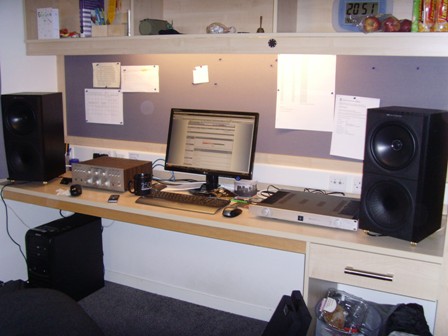 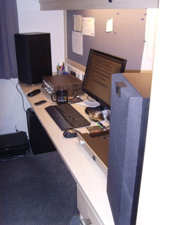 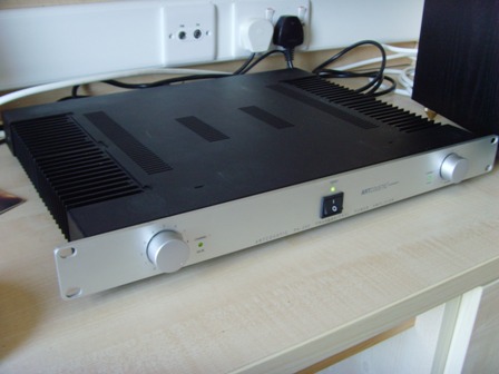 |
|
Platinum Member Username: Jan_b_vigneDallas, TX Post Number: 14864 Registered: May-04 | . http://www.stereophile.com/reference/810/index.html . |
Main Forums
Today's Posts- Home Audio Forum
- A/V Receivers Forum
- Amps Forum
- Cassette Forum
- CD Players Forum
- CD Recorders Forum
- DAC & Transports Forum
- DVD-Audio & SACD Forum
- Equalizers Forum
- Integrated Amps Forum
- iPod Docks Forum
- MiniDisc Forum
- Mini Systems Forum
- Digital Music Systems Forum
- Phono Forum
- Preamps Forum
- Speakers Forum
- Subwoofers Forum
- Tuners Forum
- Home Video Forum
- Home Theater Forum
- Car Audio Forum
- Accessories Forum
- All Forum Topics