Archive through January 06, 2008
|
New member Username: Vinny_75Post Number: 2 Registered: Dec-06 | I presume you are joking. In all seriousness, can someone please explain what symptoms one should expect on a fuse problem? Since all my speakers do work eventhough the power woofer wont work, I was wondering if it is still a woofer fuse related.. thanks |
|
New member Username: LiquidaudioPost Number: 3 Registered: Nov-06 | Dear Vinny, If you are not sure, call Bose Tech Support (800-367-4008). They can fix the unit for a flat charge. I just faced a similar problem with Acoustimass 15 bass module and first I thought it is related to fuse. I came to this forum and I opened the unit after reading other folks posting. But it was not. So I got it repaired through Bose support. Check my earlier posting on it in this forum. |
|
New member Username: Vinny_75Post Number: 3 Registered: Dec-06 | AB, Just dropped my Woofer at the service center in MA. Had to wait for an hr for a tech rep to pick it up as the service center closed operations 3hrs early today. For that inconvenience, they waived off the $75 fee and promised to ship it in 2 weeks. We will see. I have to admit..It was top class customer service. |
|
New member Username: LiquidaudioPost Number: 4 Registered: Nov-06 | Vinny: That is really cool. What can be better than a free service from Bose! -- AB |
|
New member Username: Stew_of_sedgleyPost Number: 1 Registered: Jan-07 | I recently had the centre channel go down on my lifestyle 30 system. The fix was simple. Put system into 3 speaker mode. Then adjust surround volume up to re-adjust level of centre speaker on its own. Free advice from Bose. I was amazed too. Hope this helps someone |
|
New member Username: ZshaikPost Number: 1 Registered: Jan-07 | Hi All, I have Bose Lifestyle 28 Series and my Mainunit is not working is there is any way that i can connect speekers and subWoofer with out main unit, so that i can at least i can use the rest of the Bose Lifestyle 28 Series parts. Please Help zshaik@msn.com |
|
New member Username: BrainquagmirePost Number: 1 Registered: Jan-07 | OK Fellas (and Ladies), here's more detail on the blown fuse fix: 1. You can find the 'plastic swivel tab with notches' by looking for gear teeth in the top rear of the unit. To provide some context, I've placed the subwoofer with the serial number side down, horn is up-front and treble/bass dials on the left. Remove the dial knobs. 2. Now place the unit flat with the horn-side down. Literally use a tennis shoe to spank the plastic cover (on the same side as the gear wheel) in a 45 degree upward motion so the RCA plug holes in the plastic cover are dislodged from the jacks and the unit pops off. One good spank does the job *hee hee*. 3. 2 screws will be visible at the top of the green circuit board. Unscrew these and remove cable ribbons that attach circuit board to other pieces of the unit. 4. The fuse is a cylindrical glass piece, 5mmx20mm. Mine was burnt and coils were missing, an obvious sign of a blown fuse. 5. Don't go to radio shack to find a replacement. They are seriously under-equipped to assist. Go online or to a real electrical supply store to get a 3Amp, 250 Volt 5x20mm slowblow fuse. Don't try to call Bose either because this will inevitably result in more pain. They will try to coax you to order an owner's manual for $10 to get the part number, so you can pay an inflated rate to get the same piece from them. Grrr. 6. I saved $200 - thanks to all contributors on the board. Good work. 7. If this advice helps you, do something nice to help a homeless or mistreated animal. Humans can never be too kind to the rest of the creatures on this planet. Peace |
|
New member Username: ApachedSydney, NSW Australia Post Number: 1 Registered: Feb-07 | Hi all, We approached Bose in Australia for a 230 V power supply to replace 110V supply of Lifestyle 48 sytem purchased in the US. Was told it would cost A$1600 for conversion as they need to Change ROM Drive, Radio bandwidth etc. Would like to know if anyone had similar experience and will appreciate any suggestions comments. |
|
Silver Member Username: GavdawgPost Number: 194 Registered: Nov-06 | for that price; eBay it, ship it to the USA, and start over, with Bose or with another brand. |
|
New member Username: ApachedSydney, NSW Australia Post Number: 2 Registered: Feb-07 | I would agree that starting over is a sensible idea. Problem is it has already cost appros $400 to ship it out here and will be similar cost to ship back!! |
|
New member Username: PawyQLD, QLD Australia Post Number: 1 Registered: Feb-07 | Ok so i finally worked out how to get that stupid cover off.... Found STA08-800 to not be working bypassed it.. System has power now yippie..!!! Still not a sound out of it..!!! GRRRR Its not going to beat me i swear.... |
|
New member Username: Jos_1Post Number: 1 Registered: Feb-07 | I knew Bose is crap. In my case, I found a pair of bose bookcase speakers in a garage sale for $1.00 the pair, and you guessed it, they don't work. I removed the two 4" bose speakers and they look fine, but they don't work. I went to Radio Shack and bought a pair of 4" replacement speakers for $4.00 each, installed them in the bose speaker cabinets and they work and sound fine. The incredible thing is that I have 40 year-old equipment like Fisher and even cheap stuff from the 1960's Sears catalog, and the speakers and components still work fine. (this is before "Made In Japan") Then comes an Amerrican company like Bose and starts peddling garbage packaged in designer yuppy wrappers, for unbelievably high prices, and people run to buy the caca, then their only resort is forums like these! Give me a break! Throw the bose stuff away and buy a REAL HIFI system please. |
|
Gold Member Username: NuckPost Number: 5941 Registered: Dec-04 | jos, you will fit in just fine. I like the 701's however. |
|
New member Username: Jos_1Post Number: 2 Registered: Feb-07 | nuck, thanks for the welcome, what are 701's? (my only experience with anything Bose is those two bookcase speakers! and you already know it was a crash). I am still scratching my head about those two 4" (or 4½") Bose Speakers with their very heavy magnets and rubber cones, in excellent-looking condition, but they don't sound. Yes, I still have them in the Radio Shack boxes! If they did work, I bet they would work great in a car stereo, or wouldn't they? I guess I'll just dream on.... |
|
Gold Member Username: Arande2400dB could probably d..., SouthWest Mi... Too Many DBs... Post Number: 1233 Registered: Dec-06 | I dunno, I put a little 2.5" driver in a giant enclosure and it had a whollop more bass than I expected it to have and it sounds fine. |
|
New member Username: SbnootfulPost Number: 2 Registered: Sep-06 | Does any one know how to disassemle the bose cube to be able to replace the drivers? |
|
New member Username: Jos_1Post Number: 3 Registered: Feb-07 | this might not help you but in the case of my bookcase speaker cabinets, the trick was to remove the grilles, which were heat-gun 'welded' to the front of the cabinets, and not just that, but the finishing metal decorative plate on top of the grille was contact-cement-glued to the grille, and right behind it, there was the one-and-only screw for the grille. (tacky, very tacky assembly and pure self-serving design), The only way to remove that metal plate was to pry it, and damage was impossible to avoid. Once the grille was off the dumb cabinets, then the 2 non-working speakers/woofers were removable by 3 phillips screws each. I said 3 screws, not 4. In my opinion, today's component and speaker cabinet designs are 'amateur' to say the least. Bose is the Queen of Amateur Design. One has to go back to the 1960's to find properly designed stereo equipment that SOUNDS like a Stereo. being a musician as well, I remember a few years ago when Bose tried to market a sound system for guitarists, keyboardists, and Public Address System or "PA". It was sooooo ridiculous, sounded like a tin-can-in-heat, lots of hype and marketing for a laughable product that quickly and quietly dissapeared from the scene! regards to all of you Bose lovers, sooner or later you'll find out that 'she doesn't love you'. |
|
New member Username: Diklas80Post Number: 1 Registered: Apr-07 | I own a new Bose Cinemate system. The fuse in the Acustimass module was burnt. looks like the Power PCB was also damaged. Can I get an EOM replacement PCB? Are the Bass modules the same for the Ciemate system and other Bose systems? Looking at the Bose repair price I don't fill like spending a lot. |
|
Gold Member Username: NuckPost Number: 7017 Registered: Dec-04 | Is the repair price so huge as compared to the purchase price, Yossi? |
|
New member Username: Jos_1Post Number: 4 Registered: Feb-07 | man, why bother with Bose? as if they were the only component speaker on earth! I agree they are a POS, so why don't we all show Bose by buying some other brand? I mean, here we are subsidizing that company, making them RICH, and they give us, GARBAGE. Not me! Blown fuses, un-openable cabinets, don't you all get it? Bose DON'T CARE! It's a ripoff! Adios Bose, so long, Farewell, Auf Widerssen, Goodbyeeee! |
|
Gold Member Username: NuckPost Number: 7024 Registered: Dec-04 | Is Jos actually Julie Andrews? |
|
Gold Member Username: Thx_3417Bournemouth ... Post Number: 3708 Registered: May-05 | LOL   |
|
New member Username: Diklas80Post Number: 2 Registered: Apr-07 | Does the Acustimass module of a 123 DVD system have the same power board as the Cinemate Acustimass module? How can I obtain this power PCB? |
|
New member Username: Mr3dzpopWoodstock, Georgia USA Post Number: 4 Registered: May-07 | Holy crap!! OK, Bose owners out there listen up and listen good. Here's the real scoop on 1.(getting access to the inside of most bose subwoofers, 2.( repairing said subwoofer. Follow these steps in removing the cover of your subwoofer. Unscrew the two screws from the cover. (They are on the input/output side of the cover) Remove the two knobs (Bass and treble volume). On the opposite side of the cover, (put those damn shoes back in the closet) there is a lockout tab that needs to be swung out, it moves 90 degrees in a counter-clockwise direction and is located under the center of the cover. A small flat blade screwdriver works great for swinging this tab out and will be necessary for the next step (the screwdriver that is). On the same side (opposite the input/output side) there are two small tabs near the edges of the cover, one on the right and it's counterpart on the left. If you look closely in the gap between the cover and the sub itself, you will see these 3/8" wide tabs near the edges and towards the top of the cover. With the flat blade screwdriver, put the blade between the cover and on the tab and pull down. Then with your hand balled into a fist, gently hit that side of the cover towards the input/output side. the cover will move only slightly but the tab should remain depressed. Do the same procedure on the opposite side of the cover and it will slide about a 1/2 to 3/4" towards the input/output side and can then be removed by pulling it straight up and off of the cabinet. Yay! If you get this far without incident then you are ready to implement repairs. In the case of the AM15's, normally what happens is a resistor will open up and prevent the triac (turn-on device) from firing. The fuse is on the underside of the PC board and this above mentioned resistor is a 100 ohm, surface mount "chip" resistor on the top side of the PC board. It will not appear to be bad but trust me, if the fuse is good and the sub will not turn on... replace it! You don't have to use a chip resistor since as a consumer you may have a rough time finding one but a 1/8 watt or 1/4 watt resistor you can find at any Radio Shack will work just dandy in this application. Cut the leads short and solder the two cut leads to the pads on the circuit board where the chip resistor is currently sitting. The chip resistor will be black, about 1/4" long, 1/8" wide and have "101" printed on it's surface. On some models they used two 200 ohm resistors in parallel but the result is the same. One 1/4w axial lead resistor will do just fine. Plug it up and give it a try. (Before you replace the cover). Secondly, if the fuse is blown on a "Lifestyle" Bose subwoofer, contrary to popular belief, it blew for a reason. The speaker outputs and the subwoofer output devices are TDA7294 IC's with TIP142 and TIP147 Motorola transistors used as current supplements to these said output devices. If the fuse is blown and replacing it only results in another blown fuse then chances are good that one or more of these are blown. In some cases it's very easy to tell, the front of these IC's will be blown off and/or you will see burn marks on the board where they are mounted. These devices are located inside the amp portion of the subwoofer. (The black metal heatsink underneath the input/preamp PCB. As a consumer, if the fuse is blown, unless you are familiar with soldering techniques and troubleshooting electronics, leave this to the pro's. It isn't as easy as you might think and you can destroy the PCB in your attempts to repair it. On Lifestyle 25II and Lifestyle 30II systems there is a problem with the surround portion of the sub system. Inside on the surround PCB there is a 400 MHZ crystal that clocks converted (to digital format) audio signals through the surround processing area of the sub. These crystals fail and the system, although it powers up just fine, has no output at all or it is intermittent. There are a jillion different models of Bose "Lifestyle" systems and other Bose products each with it's own quirky behavior and common maladies. If you have specific questions about a particular model or Bose system with a perceived or real problem, then email me and I will try to be of service to you. If I had 10 more bucks for every Bose system I've repaired in my lifetime I could buy a house boat. ( Not that I really want or need one) but you get the idea. mr3dzpop@bellsouth.net |
|
Gold Member Username: NuckPost Number: 7288 Registered: Dec-04 | Nice, Mark. Real nice! |
|
New member Username: Mr3dzpopWoodstock, Georgia USA Post Number: 6 Registered: May-07 | Thanks Nuck I do this every day for a living and have been working for the same company for the last 20 years. What I see a great deal of is equipment sent in for repair that is simply ESO (Equipment Superior to Operator), newer receivers that have their little brains scrambled and just need reseting and/or some simple 'wrong button pushed', 'speaker switch not on', menu setting changed accidently by a child, pet or owner. In many cases these customers are paying $50 (estimate/processing fee) for something they could have done themselves if they'd only known. Where I work, all the techs are of the mind set to be able to put themselves on the other side of the counter when it comes to customer service and because of this philosophy we have been very successful in maintaining a very trusting and loyal customer base. I would much rather talk to a customer on the phone BEFORE he/she drops off their equipment for repair and help determine if they have a real or only perceived problem. I will try to be as active on this message board as I can and be of as much assistance as possible simply because I can. With that said, I must admit that I may be taking a bit of a hiatus here soon because of sugery on my right hand little finger Thursday morning and the less than pleasant news that I will have to wear a splint on that finger for 6 weeks. So if my posts are slow in coming and the P's, quotes and apostrophes are missing, it's because my pinky has been bound, gagged and wrapped in a small coffin. |
|
New member Username: TipitinaPost Number: 1 Registered: May-07 | Does the chip resistor just plug in or does it have to be soldered also? If it can be plugged, can you possibly send one? I can send money order or paypal! While I am pretty adept at soldering, if that doesn't fix it, I will have no onther option but to send to Bose, and I am afraid they will not fix if it has a non-standard piece of equipment. Your thoughts Mark? PS Thanks for all the great info thus far! |
|
New member Username: Mr3dzpopWoodstock, Georgia USA Post Number: 7 Registered: May-07 | First of all Matt, it all depends on what model of subwoofer you have and what version of that model. There are literally dozens of different Bose subwoofers out there. The 100 ohm resistor was only in reference to the AM15's. These subwoofers are made to take your speaker level outputs from any receiver and generate the low frequencies filtered out of that input content. Only one model has the 100 ohm resistor on the top. Some of the AM15's have two 20 ohm chip resistors that will also fail and prevent the the power supply from coming on and in their case the aforementioned 100 ohm resistor is on the bottom of the board. The chip resistors in question will be located on the top of the pc board near the lower left (as your facing the sub as it would be if in use) about an 1 1/2" above where the AC socket is mounted to the board. They are sitting there all by their lonesomes so you can't miss them. The 100 ohm resistors will be black and marked with a "101" and in the case of the two 20 ohm resistors they will be parallel to each other in relatively the same area and are marked "200". In parallel they measure 10 ohms. If you have any other type of sub like a Lifestyle 12, 20,25,30,25II,30II etc etc then they work entirely different from the AM15's and AM15P's. On the bottom side of the sub it should have a label that indicates the model like Acoustimass 25 for example. Without this bit of information first, I would be leading you down the proverbial garden path. All chip resistors are soldered to the PC board. They are what is known as 'surface mount devices' meaning they have no wire leads to poke through holes and mount directly to the surface of a printed circuit board. They range in size from so small you have to view them with a magnifying glass to 1/2" long and 1/4" wide (and larger) depending on their application and wattage rating. The ones were speaking of here are about 3/16" by 1/8" and are 1/8 watt devices. All this is a moot point if you don't have one of these subs so let's get that determined before venturing on any further. As far as paying for a chip resistor, just a stamped, self addressed envelope would be all I need. They are 'a dime a dozen' as the saying goes and I'll just return to you what you need in your envelope. That being said... first things first, referring to the last part of the first paragraph.} |
|
New member Username: Mr3dzpopWoodstock, Georgia USA Post Number: 8 Registered: May-07 | May I offer some technical jargon to those Bose owners out there with lifestyle systems that refuse to power up and when checked have no apparent problem. You check the fuse and it's ok, nothing looks defective but it still has no sound. You may occasionally hear a very quick thump but that's all. With units that use the CD5 head units, you will notice that at the console end of the connecting cable there are two RCA jacks and a phone jack with a tip and two rings. When you power up the console 12 volts is sent through the phone jack cable to the subwoofer turn on circuit via several surface mount capacitors and transistors. This initial pulse will fire the triac and the ac is applied to the power transformer, the power supplies in the amp portion (below the circuit board within the black metal heatsink) come on and send +12V and -12 volts to the top board. All of your amplifiers also come on at the same time. If there is a problem with any one of these amps (5 or 6 depending on the model) then they convey that condition to the top pc board in the form of a voltage. In turn this will cause a protection circuit to take over and will shut off the power supply to the sub and the original 12 volts supplied by the console keeps this protection system latched. This is done to prevent damage to both the subwoofer electronics and the internal speaker. Systems using the CD20 6 disc changer consoles also work in this manner except the cable is different. Oh, and by the way, the other ring on the phone jack cable carries digital information to control volume, muting and all other functions of the sub. If this is the case then by all means you need to contact Bose and ship it to them for repair. I've read a good deal of "bad mouthing" about Bose and while I would never personally consider owning one myself, they are a very reputable and fair company to deal with. You won't get gouged like you could be at some mom and pop shop and you get what you pay for, it's fixed right and by people who know these systems inside and out. Just my two cents worth on the matter. 8^) |
|
Gold Member Username: NuckPost Number: 7394 Registered: Dec-04 | Mark, that much seems to be true, regarding Bose service. A goodly number of posters here have had great success and happy experiences with Bose service. As far as owning one, well... Good luck with your digit. |
|
New member Username: TipitinaPost Number: 2 Registered: May-07 | Mark, it is an AM 15, sorry! It is the older model with the round hole in front not the square. Bose support told me it was AM 15 Series 1. Is this all of the info you need? Thanks so much for all of you help! This is so frustrating!@ |
|
New member Username: Mr3dzpopWoodstock, Georgia USA Post Number: 9 Registered: May-07 | Triptina... that will work. If you can hold out till Tuesday I will be back in the office and will pull the schematic on that model and make sure I give you the correct info. I'll Xerox the page to show you exactly where to look and what to use to repair it. Yes folks, I have access to all Bose schematics but it IS as Bose says, proprietary information and I can't be providing them to the general public out of respect of our commitment to the Bose Corporation. I can help you from this end with specific info but not prints. |
|
New member Username: TipitinaPost Number: 3 Registered: May-07 | Let me know! Thanks |
|
New member Username: Mr3dzpopWoodstock, Georgia USA Post Number: 10 Registered: May-07 | OK Triptina, in your case with a series one AM15 what you will be looking for is actually a 10 ohm 1/4 watt resistor. It is on top of the board right behind where the 5 wire connector coming from the transformer is attached. It will have "100" marked in white letters if is the chip type or will have brown/black/black/gold bands on it if is of the carbon axial lead type. you can purchase one locally if you have a Radio shack handy in your area. This resistor is part of the network used to fire the triac to turn on the power transformer. It is very common for this resistor to fail. The fuse should look OK. |
|
Gold Member Username: NuckPost Number: 7432 Registered: Dec-04 | Priceless, Mark. |
|
New member Username: TipitinaPost Number: 4 Registered: May-07 | Fuse does look okay. I am going to Jamaica next week(hopefully, if I get passport......) so it will be a couple weeks, THANKS A LOT MARK!!! Will update ya after I check it out. |
|
New member Username: ForrestmcdPost Number: 1 Registered: Jun-07 | I have an AM15 series II but I'm missing the input cable. I want to make up my own cable but I am in need of the pinouts of the DB15 connector. Can anyone help? |
|
Bronze Member Username: Mr3dzpopWoodstock, Georgia USA Post Number: 11 Registered: May-07 | Forrestmod... If I had opened my email this morning I could have helped you tonight but alas I was running late and left before checking. If you can hold out till Monday evening I will get the pinouts for you for the cable. I have the manuals with that info in them. That cable is also available from Bose if you want to order one. I will get you the part number also just in case you run into problems. |
|
New member Username: ForrestmcdPost Number: 2 Registered: Jun-07 | Thank you Mark... Monday or any day next week will be fine. I just hate to spend the money on a "Bose" input cable when I can easily make up my own cable. I just need the pinouts. |
|
Gold Member Username: NuckPost Number: 7534 Registered: Dec-04 | Mark, if you are not the employee of the month at work, you are member of the month here! Thank You |
|
Bronze Member Username: Mr3dzpopWoodstock, Georgia USA Post Number: 12 Registered: May-07 | Nuck, funny you should say that about employee of the month. I suppose I will be from now on by default since our service center staff has been depleted from 18 to the current 4! I am the last man standing as far as the technical aspect of the center. Currently the service center consists of a Regional Director, Service Manager, Narda claims adjuster/parts room supervisor/product manager/shipping agent (she wears many hats during the day), and myself. I am doing all the electronic repairs consisting of any and all consumer audio and video (I DON'T DO TV's). All this reduction in staffing took place in less than 2 months and the work load at this time is overwhelming. The company I work for is (was) all over the country with the main offices located in Canton Mass. but due to circumstances that we as "peons" had no control over, the powers that be have seen fit to lay off literally hundreds of employees, closed countless retail operations and is struggling for it's very existance at this time. I have agreed to stay on until some other arrangements can be made for the service work to be shipped elsewhere in the company. At that time I too will become "unemployed" but free to do what I really love doing and that is writing "Flash" code, PHP and related programming. Not to mention, instead of the daily round trip of 72 miles to and from work (at todays gas prices) all I will have to do is walk the 15 or so feet from the bedroom to the computer. 8^) What I do on this forum is simply a product of my own personal attitude about "helping" and 40+ years of serving the general public in matters relating to electronics. My gratification comes in the form of the personal satisfaction of having helped someone solve a problem. I do hope that what I do in some small way plants a seed for the concept of "pay it forward" in those who would receive that help and maybe those who only read about it. Good grief, I sound like I'm preaching from a soap box. (Actually I'm just having fun!!) :-) |
|
Bronze Member Username: Mr3dzpopWoodstock, Georgia USA Post Number: 13 Registered: May-07 | Forrestmod... Sorry about the delay in getting this to you but the chaos where I am working is out of hand. I will send you the .pdf sheet showing you the pinout of the DB15 input side of the cable. This pinout is the pc mounted mate for the cable you wish to build yourself. Make sure of the pin numbers by looking at both the female cable you are building and the male connector on the sub. The pin numbers may be reversed on the cable you are trying to make ie. pin 1 may be pin 15 on the input. The pinouts on the .pdf are at the bottom right and ignore pins 16 and 17 as they are grounds and not actually part of the connector itself. Again, sorry for the delay and hope this helps you get the beast going. |
|
New member Username: FwtPhoenix, AZ USA Post Number: 1 Registered: Jun-07 | Hey Mark, Sorry about your downsizing problems, gone through a few of those myself. Off the topic of the Subwoofers but I have a P1 LCD Touchscreen Remote Control that the EL Panel has gone dead in. Do you know how and where to purchase a replacement part? The power inverter seems to be working just the EL is only glowing in about a 2" area. Thanks in advance for any help as this remote is no longer available and the Lifestyle 50 is not compatable with any of the other remotes. Best Regards, Frank |
|
Bronze Member Username: Mr3dzpopWoodstock, Georgia USA Post Number: 14 Registered: May-07 | Frank, Actually I have never seen a lifestyle 50 system so I will have to go to the website and get the information you are seeking. I don't know that we ever carried them but the scoop on them is available. I will check in the morning when I get to the office and will post tomorrow night with particulars. Hang in there... Mark B. |
|
New member Username: FwtPhoenix, AZ USA Post Number: 2 Registered: Jun-07 | Thanks Mark, Hope all's well with you! Frank |
|
New member Username: Eric_34Post Number: 1 Registered: Jun-07 | Hi Mark, First of all,thank you for the great tips you're giving to all the guys. I have an AM 10 Series IV system and the power transformer burned. I'd like to know the output voltages to replace it. Thanks a lot. Have a great day. Eric, Montpellier France. https://www.ecoustics.com/cgi-bin/bbs/show.pl?tpc=1&post=1185309#POST1185309 |
|
Bronze Member Username: Mr3dzpopWoodstock, Georgia USA Post Number: 15 Registered: May-07 | Hello Eric... When you say "burned" I assume you mean the transformer is "open" or do you mean physically burned? A little scary that last reference. What I can tell you is the transformer is a multi-voltage type so it can be configured to operate in different countries by just changing jumper connections on the EQ board of the AM10. There is no reference anywhere that actually shows those voltages so that question cannot be answered. I can get you a part number for that transformer and may even have one somewhere that I could get to you, this I would have to check on. Are you absolutely sure it's the transformer that is defective? It is rare that they fail so I am a bit concerned that you may be barking up the wrong tree here. I will look for a response from you here at the forum but make it quick since I am leaving for south Florida Tuesday morning the 3rd and won't be back in town until the 10th. |
|
New member Username: Eric_34Post Number: 2 Registered: Jun-07 | Thanks Mark for your promt reply. The AM10 worked 2 days, then stopped. I checked the Xformer and the primary was open. It was the thermic switch. I bypassed it, and then plug it back leaving the output unplugged,but the fuse blows up. I contactted the maker (Billion in Taiwan) but didn't want to sell or give any info about it. https://www.ecoustics.com/cgi-bin/bbs/show.pl?tpc=1&post=1191097#POST1191097 |
|
New member Username: PoloflyingAustralia Post Number: 1 Registered: Aug-07 | hi Mark, I have a lifestyle 25 cd stacker and a cd jammed the other day, I managed to retrieve it but now the it doesn't recognise that there is anything in the emagazine and keep's hunting for them up and down without finding anything. is there a fix here or have I broken something. thankyou |
|
Gold Member Username: NuckPost Number: 8268 Registered: Dec-04 | Paul, you have likely dislodged the disc sensor. This does what it's name says, senses disc in transport. You can put it back in line if you open it up, it ain't real hard. Next time, don't be so ham-fisted with the thing. |
|
New member Username: PoloflyingAustralia Post Number: 2 Registered: Aug-07 | hi Nuck, thanks for that..... I found that I had dislodged a gear and the mechanics of engagement now work but I now find myself with an alignment problem. When I try to eject the cd, it seems to be a bees out. if i gently..... push down on the cd it goes into the slot below and ejects nicely. this would be fine if I wanted to leave the cover off but alas not a good look on the plasma stand. any help is gratefully appreciated. regards, Paul |
|
Bronze Member Username: Mr3dzpopWoodstock, Georgia USA Post Number: 16 Registered: May-07 | Paul Your CD changer works by pushing a small thin piston like device to start the CD extraction. It operates in the same way you remove the discs from the cartridge. The rollers turn and if there is a CD in the slot, it is moved into the mechanism. The disc sensor Nuck was speaking of then detects that there is indeed a disc being loaded. If you have bent that arm and/or gotten the elevator assembly out of time then the CD is not properly lined up when you attempt to eject it. You may also have knocked one of the springs off the rollers. There is a small spring on either end of those rollers that applys the pressure to the disc to either load or unload it. This is a hard one to diagnose without having the mech in hand and not knowing what gear you knocked loose makes it hard to steer you in the right direction. If the elevator is out of alignment then the disc is not centered in front of its slot and when the eject arms at the back of the mech try to push it out to engage the rollers, the CD may never come into contact with them. Result, no eject. If you can be a bit more explicit with which gear and what you did to get the disc out maybe I can be of more help. |
|
New member Username: PoloflyingAustralia Post Number: 3 Registered: Aug-07 | Hi Mark, many thanks for your expertise. I have uploaded a2 photo's for you to look at. The gear I dislodged is the one bottom right in the close up. If I push up slightly on the cross levers on the outer casing whilst trying to eject the cd it then goes into the proper slot and ejects nicely. when I first had the jam, I pushed down quite heavily and moved the rollers by had to eject the cd. I think i may have done something harsh. thanks agin for your and everyone's help witht his. regards, Paul O. 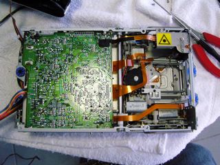 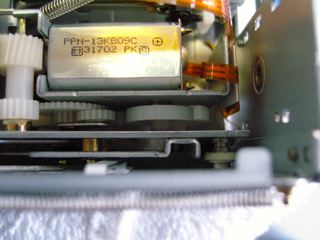 |
|
New member Username: PdinellaPost Number: 1 Registered: Aug-07 | First off great thread. Now to the question. I have a lifestyle 12 system and everything works great but the digital input. I have tried like three different devices with two different cable. I hadn't used it for a while and then tried to use it like a month ago. I am hoping that there is just something I can reset. Any help would be appreciated. |
|
New member Username: Eric_34Post Number: 3 Registered: Jun-07 | Hi to all, anybody could give me these output voltages for the power transformer of an Acoustimass 10 sub woofer ? Thanks to all |
|
New member Username: KamagongManilaPhilippines Post Number: 1 Registered: Aug-07 | Hi,... I own a BOSE 301 SERIES IV and a BOSE ACOUSTIMASS 10 SERIES II, both broke down. Anyone who can help me out with the schematics for both SERIES? I would really appreciate anyone's help. Please if so mail me. Thanks |
|
New member Username: KamagongManilaPhilippines Post Number: 2 Registered: Aug-07 | Hi,... I own a BOSE 301 SERIES IV and a BOSE ACOUSTIMASS 10 SERIES II, both broke down. Anyone who can help me out with the schematics for both SERIES? I would really appreciate anyone's help. Please mail me. Thanks |
|
Bronze Member Username: Mr3dzpopWoodstock, Georgia USA Post Number: 17 Registered: May-07 | Paul, You say you have a Lifestyle 12 system but I don't remember the CD5 having a digital input. Is it Coax or optical? Also you need to check which version of the CD5 you have. You can do this by checking the bottom of the console and giving me the scoop on what's written there. There are several different versions of this same console and although they operate the same the guts are totally different. |
|
Bronze Member Username: Mr3dzpopWoodstock, Georgia USA Post Number: 18 Registered: May-07 | To those others with Bose questions, I apologize for not being on here much of late. I've been working two jobs and haven't had much spare time at all. Eric and John just hang in there and I will try to have the stuff you need tomorrow night. (Friday, August 24). John, I will have to send you the series III manual for the Acoustimass 10 since the series II schematic is not available. I'm sure they're similar enough to help you. The 301 series IV is no big deal as it's passive and all you have to deal with are the crossovers and bad speakers possibly. Eric, while I can't tell you the exact output voltages for the power transformer, I can send you the .pdf with the supply schematic and you can figure from there. Pins one and five (blue)should be around 57VAC and pins two and four (yellow)around 28VAC. This would give you 57/.707 ~= 80VDC center tapped and the other 28/.707 ~= 40VDC center tapped. Pin 3 (gray) would be the center tap and is your ground reference. Thanks for your patience, I'm an old guy and don't get much time for myself. :-) |
|
Gold Member Username: NuckPost Number: 8440 Registered: Dec-04 | Mark, just offering all this help is really cool. Don't burn out, man, lot's of help needed here. Cheers, Mate. |
|
New member Username: PoloflyingAustralia Post Number: 4 Registered: Aug-07 | Hi Does anyone know if I can run a lifestyle 18 dvd player through my lifestyle 25 sub and speakers?, the din cable from the back of my cd stacker is the same as the 'in' on the 18 dvd player. thanks, Paul O. |
|
Silver Member Username: GavdawgUpstate, New York Post Number: 871 Registered: Nov-06 | as far as I know, it is the same unit, Paul. |
|
Bronze Member Username: Mr3dzpopWoodstock, Georgia USA Post Number: 19 Registered: May-07 | Paul, In a word... NO! I don't think it's such a good idea. While most of the pins on the din connector are compatible there are a couple of pins that would cause havoc with the LS18. Also you will note that there is one extra pin on the AV18 that your CD20 doesn't have.(pin 9) Zone 2 output is even worse because of the signal pinouts. If you will email me I will return the two prints that show the pinouts of the CD20 and the AV18. You will be able to see the differences I'm talking about. |
|
New member Username: BrbosePost Number: 1 Registered: Sep-07 | Hi Mark and others, My friend asked for my help on fixing her bose companion 3 series II multimedia speakers. This set is originally bought in the U.S. then brought to the U.K. She accidentally plugged it directly to 220Vac supply and now the unit will not turn on. I tried opening the sub but is unable as I am afraid of damaging it. Any special procedures on opening the box so I can check the fuse? Or maybe if you can give me an idea what else to check? I'll wait for your reply. Thanks in advance. Regards, |
|
Bronze Member Username: Mr3dzpopWoodstock, Georgia USA Post Number: 20 Registered: May-07 | Berwyn... As you've no doubt found out, just removing the obvious and visible screws in the sub, doesn't allow you to get into it. In addition to removing them, you must also remove the volume knob and VERY CAREFULLY remove the plastic label on the amp assembly. There are screws that need to be removed that are covered up by this label. There are three of them running down the right side as you face the amp panel. In all you should be removing 8 screws from the back and then you will be able to get inside to the electronics. Once you've accomplished this, carefully tilt the amp assembly out and you will find two connectors preventing it from just coming out all the way. You need to disconnect these two connectors. One is going to the woofer and the other to the transformer which is mounted separately. Once out you will have access to the fuse you are looking for. Let me know how you progress. |
|
New member Username: BrbosePost Number: 2 Registered: Sep-07 | Hi Mark, Thank you for the reply. I will try to open it today. By the way I read the power requirement for the Bose companion and it says 120Vac 60Hz, but the stepdown transformer that we bought is 50Hz, will this work? Or do we have some setting in the Bose transformer to make it 50Hz? Thanks again. |
|
Bronze Member Username: Mr3dzpopWoodstock, Georgia USA Post Number: 21 Registered: May-07 | Yes, the transformer you purchased will be just fine. The Bose will operate on 120v 50-60 Hz. Line frequency is not something you have any control over; it is what it is depending on what country you're in. |
|
New member Username: Fred333Post Number: 6 Registered: Oct-07 | Man this why I do not buy Bose products. If something goes bad in them it is tough to fix. |
|
New member Username: NiilarteLondon, London United kingdom Post Number: 1 Registered: Oct-07 | hi Mark, I bought a bose 321 gs ii dvd system from the US and brought it to the uk. I purchased a transformer form Maplins electonics which worked OK. But last week the base unit stopped supplying power to the media unit. Bose want £375 ( $ 800) to fix it as they said that it will have to be converted from US voltage to UK 240v . THe system is just 4 months old. Any ideas on how i can fix it. Thanks David |
|
New member Username: BrbosePost Number: 3 Registered: Sep-07 | Hi everyone, First of all many many thanks to Mark for sharing some info to us all. Bose UK qoute £150 for the conversion by the way and they told me that just using a stepdown transformer from Maplin won't work because of the line frequency. Hi Mark, My sincere thanks. I managed to open the Companion 3 and luckily it's just the fuse that was busted. The system is working okay now with the stepdown transformer that we bought. My only problem now is that I damaged the sticker. Can we order this sticker from Bose? Regards, Berwyn |
|
Bronze Member Username: Mr3dzpopWoodstock, Georgia USA Post Number: 22 Registered: May-07 | Berwyn, Yes you can order that face plate from Bose. The part number for that label is 300954-001. Description: Label, I/O US/Canada, 120V. It comes with a peel off back. Use caution when installing it. I usually just peel back one corner, position it correctly and press the corner I've peeled. Then carefully, while you pull the backing off press it in place, smoothing it with your fingers as you go. This will make it go on smoothly and without air bubbles trapped behind it. If you should get an air bubble, DON'T peel it off and try again. Take a needle and poke a tiny hole in the center of the bubble and then press it flat and the air should escape out the needle hole. Hope this helps. Mark B. |
|
Bronze Member Username: Mr3dzpopWoodstock, Georgia USA Post Number: 23 Registered: May-07 | And to you David, Bose is out of their friggin minds. $800 to convert to 240V? Absurd!! And line frequency schmequency. Almost all US made equipment will work on 50Hz or 60Hz. The only real consideration is if the device in question uses the frequency as a time base for some reason like an electronic clock. I'll look into the specific requirements for that unit and get back to you Saturday sometime. I am working at a new job and don't get to my old place of work except on Saturdays now. In the meantime you might want to take the plastic cover off the sub and see if the internal fuse is open. It may be all it needs. There is absolutely no reason why the transformer you bought shouldn't work as long as it has an adequate power output for the device you are running. Send me the specs for the transformer you bought and I'll see if it is indeed suitable. Mark B. |
|
New member Username: JjfenceJapan Post Number: 1 Registered: Oct-07 | Thanks everyone for all of the posts on this topic. Have a 5-yr old acoustimass 15 and after my recent move the connections to the sats worked fine but my subwoofer wouldn't power up. After removing the screws and the knobs and turning the little tab I struggled with the case before finally giving it one hell of a whack! to get it open. The fuse doesn't have the simple metal filament inside, but what looks like a glass filament with a wire wrapped around it. While the transparent (glass?) filament seems to be in one piece, the metal wire looks like it may have burned up in the middle so I'll try to replace that tomorrow. Hopefully it's just the fuse since the unit's been great for my needs so far and I'm not really ready to spend big bucks on a new systems just now. |
|
New member Username: Malv16Post Number: 1 Registered: Oct-07 | Hi Mark, I have lifestyle 30 series 2. But the lifestyle unit was crushed by our mover when we shifted place. So, I am left with the active sub and 5 sats. Is there anyway I can DIY the 13 pin cable to connect it to DTS decoder or preamp? my email syncmaster172ss@yahoo.com |
|
New member Username: TomttomPost Number: 1 Registered: Oct-07 | Mark, I have a 230V Powered AM20 and an M1 Multiroom Interface. Due to some unreliable contact we had to fix the interconnect cord between the two and the AM20 wouldn't power up any longer. I don't know if there's any coincidence. I opened the AM. Fuse was ok. I have an LCD remote called P1 Personal Music Center. There's a 8 pin mini DIN plug on the MRI side and a 5 pin DIN on the AM side. According to some drawing the signals are: variable audio left/right, grounds and power on (+10V). It seems logical to suppose that when the 10V is present the subwoofer should power up. However we couldn't measure 10V on the corresponding pin. The MRI somehow still senses the AM because the LCD can only be used if the AM is connected to the MRI. If I unplug the interconnect cable it starts searching and no control is possible. I even tried to short the A1 and A2 legs of the triac but nothing happened. Could you shed some light on how the two units sense eachother and which one of them could go wrong? Any tips on how to proceed? Thanks, Tom |
|
New member Username: Mtroy59Post Number: 1 Registered: Oct-07 | Thanks to all for this invaluable board! Esp Mark!! To those who need a replacement part including cables. I have sent to Bose for replacement cables and cube speaker covers. The prices are pretty fair considering the name. You either have to send them the broken part or have an excuse and a p/n s/n. |
|
New member Username: KikevPost Number: 1 Registered: Nov-07 | hi i'm looking for the pinout of the lifestyle 28 system the audio input cable from the head unit to the bass module. any help will be greatfuly recived. |
|
New member Username: SunfishPost Number: 1 Registered: Nov-07 | Thanks for the info, I found this site looking for information on how to open my sub-woofer. Found the plastic swivel in the middle at the top, but the key is to lever the two little catches on the side (on top) to enable the cover to slide down. No banging or hitting with shoes or rubber mallets! Can provide a photo if anybody is interested. |
|
New member Username: Kimba07Post Number: 1 Registered: Dec-07 | Darn, I should have spent more time on the web searching for threads on DIY to potentially save big bucks. I inherited Bose Lifestyle 12 which I suspect the AM might have a blown fuse re: no bass coming out of the AM. I just took it in to this Bose authorised service center. They logged the problem as per my description "No bass coming out of the AM unit". They printed a work docket for me and says it takes roughly 10 days to fix it. They said if the cost of fixing it exceeds 145.00, they will call and ask if I wanted it fixed. If I say no, they will charge 45.00 as service fees. Worth thing is, the music centre LED doesn't display any more. So they've created 2 work dockets instead of one. I think this could potentially be a scam. Darn, this thread would have save me heaps and I am praying they are honest enough to charge me minimum labour with replacing a cheapo fuse. |
|
Bronze Member Username: Mr3dzpopWoodstock, Georgia USA Post Number: 24 Registered: May-07 | Kim... The problem with your music center is a very common one and easily fixed with one capacitor. The display is not LED but a flouresent display and the filiment voltage for it is coupled with a capacitor. It is on the top PC board on the left hand side. The value is 33ufd @63VDC. If Bose charges you for anything else then they're pulling your leg. That cap opens up after time and if the music center was working OK before, I suspect it lost power and would not appear to come again. It is actually working but you can't see the display to indicate that it is. As far as the bass unit is concerned, that could be anything including not getting the 12 volt turn-on signal from the music center. Good luck with Bose. |
|
New member Username: Ace0921Post Number: 1 Registered: Dec-07 | Mark, Question for you or anyone else with BOSE wiring experience. I just bought a Bose AM 9 speaker set that I thought was a great deal. Came with the bass module, 5 double cubes, all the original wiring and special cable that goes to the receiver. Heres the issue. My receiver is a Sony that only accepts bare wire speaker wires. I ran the wires from the cubes to the sub. Then I connect the round DIN connector to the sub, then I am supposed to connect the other RCA ends to my receiver..right? I think this speaker set went with a specific BOSE lifestyle system right? Because it only has a red, a white RCA connector and a little mini phono plug on it. I might have gotten a great deal but I don't think these will work on my receiver. Am I right? Is it possible to get a wiring diagram on the pins in that mini DIN so I could connect the sub to my receiver? The mini cubes are bare wire connectors so they could connect directly to the receiver but the sub is another issue... HELP...someone. Mike Jones |
|
Bronze Member Username: Mr3dzpopWoodstock, Georgia USA Post Number: 25 Registered: May-07 | Mike, I think you're in for a rude awakening on this one. Without the CD5 console you are going to be hard pressed to get this thing to work. The console provides not only the 12 volt turn-on voltage for the sub but also provides the digital information to control the volume and surround mode for it also. All the surround functionality of the system is within the confines of the AM9 subwoofer electronics. Wish I could be the bearer of better news but those are the facts. Bose does make systems designed for non-Bose receivers. The AM15 and AM16 are just such beasts but are not even close to the architecture of the AM9 except for the amp section. |
|
Gold Member Username: NuckPost Number: 9476 Registered: Dec-04 | Mark, you are a dandy help for these folks here. Thank you for being great for the Bose help-needers here. I wish you the best Christmas and Happiest New Year! |
|
New member Username: AmoldcPost Number: 1 Registered: Dec-07 | I have a AM10-III Subwoofer that I would like to convert from 110V to 230V AC. Can someone help me with this please? I hate to throw this expensive piece of junk. |
|
Bronze Member Username: Mr3dzpopWoodstock, Georgia USA Post Number: 26 Registered: May-07 | Well Amoldo don't throw it out just yet. There is no mod for your existing sub except for the purchase and installation of the proper transformer. The Bose part number for that is 264869 and presumably can be ordered from Bose direct. Since the transformers are plug in, all you have to do is to exchange the 240V version with the one that is installed now. There is also a small change that has to be made to the PC board and involves removing two "0" ohm resistors from R3 and R7 and installing two 130 ohm resistors in locations R2 and R6. If you will email me I will send you the documentation in .pdf format so you can visually see where these components are on the board. They are marked on the board but just in case... |
|
New member Username: AmoldcPost Number: 2 Registered: Dec-07 | Thanks a lot Mark. Appreciate if you can email me the information. my email is amol.choukekar@gmail.com Also how can I order that part from Bose? Thanks once again. |
|
Bronze Member Username: Mr3dzpopWoodstock, Georgia USA Post Number: 27 Registered: May-07 | OK Amoldo, check your email. 8^) |
|
New member Username: RickleefunPost Number: 1 Registered: Dec-07 | I have a Bose Lifestyle Model 5 and it has worked fine until now. It will power on and work fine for 30 seconds then it powers off. I can unplug it and it repeats this problem. Any ideas? Also the display does not work but the unit played fine before the power cutoff problem started. Is this easily fixed? I was thinking it was the wall transformer for the control center but don't want to just start replacing parts. Any help is appreciated. |
|
New member Username: ShowpiecerodentSutton Coldfield, West Midlands UK Post Number: 1 Registered: Dec-07 | Mark, some advice please. Thanks in advance. I have had an AM 15 system for 3+ years, In that time, I have had to replace the internal fuse 12 times. The sub will work happily for several months and then - no bass!! I chose the same rating of fuse - 1.25A - time lag 250V. My system is a UK spec. Have you met this problem before? Is the rating of the fuse correct? Your help in this thread is brilliant! Regards Showpiecerodent |
|
New member Username: Lestat0521Post Number: 2 Registered: Dec-07 | Hey Mark i picked up an older acoustimass 9 and want to hook it up to my existing receiver, can you send me a pdf with the pin layout so i can save myself some cash and just wire it up myself. Thanks! tsa_zero@hotmail.com |
|
New member Username: Lestat0521Post Number: 3 Registered: Dec-07 | after doing some reading, does anyone know if it is even possible to hook up the acoustimass 9 to a non bose receiver? |
|
New member Username: OlofPost Number: 1 Registered: Jan-08 | Hello all! I would like to connect my new set of jewelcubes to my 5.1-amp but I have heard that there might be a risk of "burning" my jewels if I connect them directly to the amp? I suppose that I have to build myself a crossover-filter, does anyone have schematics for the filter for the satellites in the passive sub used in a Acoustimass-system? Is it a couple of capasitors like a regular crossover-circuit? If I would like to set the crossover to about 280Hz, how big capasitors do I have to use? Does anyone have a idea for a subwoofer that goes up to 280Hz? Any help is appreciated! With best regards |
|
New member Username: BrowncPost Number: 1 Registered: Jan-08 | Mark, I have a Lifestyle 12 with the display INOP problem. I opened the console and nothing jumped out at me indicating it was THE 33UFD @63VDC capacitor as described in your earlier post. Would you happen to know what the component number on the board (c####) is? Also, could you point me in the right direction to purchase one? I searched the WWW for about an hour the other night without any luck. Any additional help is truly appreciated and Thank You for all the wonderful information you've provided everyone in this forum. One other question, how difficult do you think it would be to rewire\convert the speaker portion of the system to 5 independent channels to support an alternative receiver? |
|
New member Username: OlofPost Number: 2 Registered: Jan-08 | Charlie: For your second question I think you have the same problem as you (my last post). I think that you have to use a crossover-filter to prevent the small satellites from getting all frequencies that will cause unnecessary heating of your elements that in worst case will burn your satellites. I my question above I wonder if anyone could tell me how big the capacitor is for every "satellite-outport" in a Acoustimass... Without being an electrician I "think" I should use a 68MicroFarad capacitor connected in serial with the + for the satellite to make the crossing at about 294Hz. It would be GREAT if anyone could confirm this information or show me a picture of the crossoverfilter in an passive acoustimass... Hopeful of getting answers  Regards |
|
New member Username: MeunierPost Number: 1 Registered: Jan-08 | Mark, I am troubleshooting an AM 25 series II system for a friend. It works fine when cold but when it warms up all speakers kick out. Does this sound like the protection system? Possibly a resistor. Any ides how to locate it on this system? |
|
Bronze Member Username: Mr3dzpopWoodstock, Georgia USA Post Number: 28 Registered: May-07 | OK, in order let's see what we can do here. First of all Chris L., forget trying to hookup an AM9 to another receiver. You'd be biting off more than you can chew. The sub needs and external 12 volts sent to turn it on and you need the correct digital input to control the volume. Look for a AM10 or AM15 as these were designed to be used with any receiver. Yes Olof, I wouldn't want to burn my jewels either! The crossover filtering in a passive acoustimass is very complicated and involves the use of FET's and assorted other components. If you want the schematic I will send it to your email address if you email me. I can neither confirm or exclude the use of 68ufd caps for a crossover. Remember though you have to use non-polar caps and they need to have a rated voltage of at least 100V. Charlie, the cap you are looking for in your CD5 system is on the extreme left, top board. (Below and to the left of the display) The cap is C19 and may be a 33ufd @25VDC if it's the original part. You can use a 33ufd or 47ufd @50VDC and they both will work just fine in that application. Forget trying to convert anything, it just isn't feasible and you wind up creating more problems than you can think of. And finally... Todd. Todd I sent the files you need to your email address and I will add my comments to you here. "This being a series II AM25 means it falls into the failed crystal category. Your symptoms fit the mold exactly. What you are no doubt going to have to do is to replace CR400 on the top PC board. It is located underneath the shield on the component side (the one facing down when installed in the subwoofer) of the board. I am enclosing the scoop on that particular problem, the part number and the associated files to help you locate the part on the board. Hope this helps you with your problem. " OK everyone, I'm going to grab a bite to eat... 8^) |
|
New member Username: BrowncPost Number: 2 Registered: Jan-08 | Mark, Four words....Woooo Hoooo! and, Thank You! I've been without a display on my Lifestyle 12 since 1999 or 2000. At one time I considered putting it in for service for $100. I'm glad I didn't. With your help, a $1.50 part, and a $4.00 solder sucker, I was able to fix it myself! BTW...I ran up to Radio Shack immediately after reading your post and bought a 47ufd @35VDC capacitor (it's the closest they had and it was in between what you suggested). And, in 15 minutes, I was up and running. Thank you again. [:o) |
|
New member Username: Ddaggett1Post Number: 1 Registered: Jan-08 | Mark, I have a Bose LifeStyle 50. Is there any way to configure this to play DTS output from my DVD player (e.g., an external DTS decoder)? If so, can you recommend hardware to do this? If not, and since the speakers work great, is there something that I can replace the LS 50 main unit with that has a built-in DTS decoder and will still drive the speakers? Thanks! |
|
New member Username: ShowpiecerodentSutton Coldfield, West Midlands UK Post Number: 2 Registered: Dec-07 | Mark, some advice please. Thanks in advance. I have had an AM 15 system for 3+ years, In that time, I have had to replace the internal fuse 12 times. The sub will work happily for several months and then - no bass!! I chose the same rating of fuse - 1.25A - time lag 250V. My system is a UK spec. Have you met this problem before? Is the rating of the fuse correct? Your help in this thread is brilliant! Regards Steve. |
|
Bronze Member Username: Mr3dzpopWoodstock, Georgia USA Post Number: 29 Registered: May-07 | David, DTS is a format in the same way Dolby Digital is a format. As such it has to be selected from the DVD menu if that said DVD in fact has been encoded with it. Most DVD's at least within my experience are Dolby Digital or DD AND DTS encoded. If your DVD player is not designed with the capability to decode the DTS then you're out of luck. I find it hard to believe that the AV media center does not have that capability. Are you sure you don't already have that capability and haven't found out how to utilize it? Check your media center owner's manual and you may find that you have everything you need already. |
Main Forums
Today's Posts- Home Audio Forum
- A/V Receivers Forum
- Amps Forum
- Cassette Forum
- CD Players Forum
- CD Recorders Forum
- DAC & Transports Forum
- DVD-Audio & SACD Forum
- Equalizers Forum
- Integrated Amps Forum
- iPod Docks Forum
- MiniDisc Forum
- Mini Systems Forum
- Digital Music Systems Forum
- Phono Forum
- Preamps Forum
- Speakers Forum
- Subwoofers Forum
- Tuners Forum
- Home Video Forum
- Home Theater Forum
- Car Audio Forum
- Accessories Forum
- All Forum Topics