Archive through July 06, 2008
|
New member Username: RicardolozanoPost Number: 7 Registered: Jan-08 | Hi again, I'm still having problems with te bose ps28II subwoofer, If i plug it it directly to the wall (127 v ac) it only works for about 5 min, but if i put a light bulb (100 w) in series to the power cord , it works nice all the time, but the Big Problem is that I can't raise it more than volume 35, can somebody help me pls with this? I've changed many parts and still no have good results. I've changed the following; 2 mosfets and put 2 K2842 (12amp a 500v) 1 L6598D 2 times 2 10 ohm and 100 ohm mini-resistors 1 cap .47uf C119 that connects to the 14 and 16 pins of the L6598D that marked 100kohms that was a bad part and it was replaced too. 1 K72 (little mosfet Q103) and put a 2N7002 changed also the bridge rectifier to another one with more amps of capacity (600v a 35 amp) just to be sure that is better and I don't know what more parts I've to change pls. help urgent Richard Thanks a lot |
|
|
New member Username: Mauricio_buenfilPost Number: 1 Registered: Mar-08 | Hello Mark...I bought a Companion 3 Series in St Louis and brought it London: one of my flatmates plugged it into the 220V and turned it on. Nothing happened and he says that the led on the pod lit on orange and then went off. Is there something I can do to repair it? Bose UK won't take the system because it was not declared through customs...just wanted to know if there is any solution to this since i have not been able to enjoy it! Kindest Regards, Mauricio |
|
|
Bronze Member Username: Mr3dzpopWoodstock, Georgia USA Post Number: 64 Registered: May-07 | Mauricio, Hopefully all that has happened is that an internal 1 amp slo-blo fuse has opened up. If you will email me I will send you the service manual that will show how to get into the beast. There are some hidden screws and you will have to carefully peel the label off the back in order to access them. If a fuse does not correct the problem then we'll proceed from there. I suspect when it got plugged in, the supply came up (very) briefly, the caps charged up and the fuse went south. That's why the LED glowed for a few seconds and then went out... the caps discharged. |
|
|
New member Username: TznPost Number: 1 Registered: Mar-08 | Hi Mar About three years ago I bought the Acoustimas 10 III. I brought it overseas and had it converted to 220volts at a Bose repair shop. Ever since I started using it there has been a low whispering sound (like hhhhhhhhh)coming from the subwoofer. It's low but I can hear it and it is irritating. When I turn the volume down, the sound dissapears after 4-5 minutes. And when I turn it up again to a certain level, the sound comes back. Also when I have the volume set at a low level, the bass dissapears after a the same 4-5 minutes. Any ideas about what this can be, or is it just the way it comes? Thank You, Frank |
|
|
New member Username: GuggiePost Number: 1 Registered: Mar-08 | Mark, I've done my reading on here and think you can help me. I've got a Lifestyle 20 system and that should mean that I have a CD20 main unit. My display is dim and I'd like to try to do some power supply fixing first before I give up and assume it's the display tube itself. I've read the capacitor replacements that have been on other units, and would like to know what ones you suggest I replace on my unit. The board that is mounted on the left side of the main board, vertically, seems to be the supply board. Indeed, it has a connector that is labeled ser-in, ser-out, -30v, -24v, etc. I also see three caps numbered c18, c20, and c21, all 100ufd. There is a smaller one in the area as well numbered c30. Are these the ones? What am I allowed to use as replacements? Thanks. Doug |
|
|
Bronze Member Username: Mr3dzpopWoodstock, Georgia USA Post Number: 65 Registered: May-07 | Doug, Well I'm impressed! You zero'd in on most of what needs to be changed but I would also change C15, C24 and C27. So C18,C20,C21,C24 and C27 are all 100ufd @ 50V; C30 is a 2.2 at 50V but it won't be the problem. C15 is also a candidate since it couples the AC to the supply circuit for the display. C15 is a 470ufd @ 25VDC cap. Replace all the above caps with either 100ufd or 120ufd, 50V caps and C15 with a 470ufd, 25VDC or 50VDC (size permitting) cap and your display will be as bright as it's going to get without replacing it. Hope this does the trick. Mark |
|
|
Bronze Member Username: Mr3dzpopWoodstock, Georgia USA Post Number: 66 Registered: May-07 | Frank, I will take the "hhhhhhh" to be 50 or 60 cycle hum. I need for you to open the subwoofer and inspect the top PC board. There are so many fly-by-night repair shops out there it's frightening. I need to know if R3 and R7 have been changed to 130 ohm resistors and if the transformer is correct. These little resistors will be found near the front of the PC board near where the AC line comes in. There is also a small transformer in that region. The Bose part number should be on the main transformer (mounted off the PC board and connected with a 5 wire cable) and should be a 6 or 9 digit number. You may have to remove the plastic shroud covering the amp section to get to the transformer well enough to read the part number. The two resistors should be surface mount type and have 131 printed on them or they may be axial lead type and the color code will be brown,orange,brown,gold. If the surface mounted resistors have "000" printed on them then there's a problem. Find this out first and then get back to me. |
|
|
New member Username: GuggiePost Number: 2 Registered: Mar-08 | Hi Mark. I did as you suggested, replacing 6 caps in my CD20 unit. I can now see my display! It's not brilliant, and the "1" in 100.5 is slightly dimmer that the other digits, but it is a 90% improvement. Thanks for the advice. I hope I don't need any more repairs soon. I did the pinion on the motor that transports the CDs a year or so ago. |
|
|
New member Username: TznPost Number: 2 Registered: Mar-08 | Hi Mark. I am Norwegian and maybe this is an example of what a language barrier can do. When I think about it, maybe "hhhhhh" is not the best description of what the sound is like, as you pronounce "h" in a different way than we do over here. Maybe "phffffffff" is a better way of describing it. I am sorry if my description was poor. The sound clearly comes from the speaker of the sub, not the transformer. I have looked at the PC board but I can't find R3 and R7. The part number on the transformer is 264868-001. It also has 91 TS-024A written on it. I really appreciate your help, and it would be great to find out of this problem. Thanks, Frank |
|
|
Bronze Member Username: Mr3dzpopWoodstock, Georgia USA Post Number: 67 Registered: May-07 | Frank, I checked the schematic and the transformer is the correct number so I have to believe that the update was done correctly. If you will send me an email I will send the schematics and the board layout to you. I've got to admit that "phfffffff" means nothing to me. Here in the states "ph" can be pronounced as an "f" too so I am perplexed by that sound reference. In any case I think your problem is related to capacitors that are either dried out or defective. I'm not sure how to tell you to proceed but let me get the prints into your hands first and then I can reference things to check. Mark B. |
|
|
Silver Member Username: MagfanUSA Post Number: 164 Registered: Oct-07 | Does he mean a frying egg noise? Kind of a crackly hiss? |
|
|
New member Username: Yeh0565Post Number: 1 Registered: Apr-08 | I have a Bose Lifestyle Model 614810 with subwoofer Acoustimass Model 2683. There is no sound from the subwoofer as well as left & right speaker. I have check the the fuse in the subwoofer were in order. When I connect a speaker or headphone to the music center, I can hear sound comming through it. Therefore I presumed the player were in order. The fault lies in the subwoofer. I have read some thread here that the music centre have a 3.5mm plug that supply 12VDC to turn on the subwoofer. They are there alright. If anyone have the schematic to share that can foreward to yehpy@hotmail.com. This the the PCB board of this model.
|
|
|
New member Username: Musicologist1964Post Number: 1 Registered: Apr-08 | Hi, I'm wondering if you could help me recovering from a lightning strike that has damaged my Acoustimass module. The Acoustimass module is from a Lifestyle 20 system (serial number LSM20CU107173) and it is totally dead following a recent lightning strike. I have dismantled the unit and have found the damage on the "main" PCB. By "main," I mean the PCB that has the power connection, the output to the satellite units and the input from the music centre. On the underside of the main PCB, near the outputs to the satellite units, is a three terminal surface mount device. What's left of it looks similar to other devices on the PCB with "RA75" printed on them. This appears to be the only damage. Is it possible for you to identify this component and suggest a suitable replacement? I could email you a photograph of the PCB if that would help identifying the component. Cheers, Garry  |
|
|
Bronze Member Username: Mr3dzpopWoodstock, Georgia USA Post Number: 68 Registered: May-07 | Gary, Yes it would be helpful if you email me a photo of the board and a sense of just where this "component" is in relation to the board. From your description it sound like D412 but that really doesn't make any sense because that particular component would not normally be affected by a lightning strike. I can almost assure you that a single component failure is not what you're looking at. There will be other surface mount devices that are either shorted or destroyed and without proper testing equipment (a digital VOM at the very least) you will not be able to determine what is good and what is bad. There is also the path that needs to be taken into consideration. If the surge came in on the AC line then there are certain things that would be affected and if it came in from the console then the list will be different not to mention the possiblility that there may also be damage to the console. I know, it probably powers up ok but there is the matter of the 12v turn-on supply that needs to be sent to the sub to turn it on and this section of the console can go toes up in the event of a lightning strike. It would not affect the console per se but it would prevent it from controlling the sub. Send me the picture and we'll go from there. Sorry if this sounds daunting but lightning has no favorites! |
|
|
Bronze Member Username: Mr3dzpopWoodstock, Georgia USA Post Number: 69 Registered: May-07 | Danny, Alas, those model numbers mean nothing to me nor can I find any reference to them. From the looks of the picture you uploaded this is a very old piece. I'm not sure there is any information that I can get online that covers this model but I do have the old hardcopy manuals covering the old stuff Bose carried. Try to find some kind of model nomenclature on the units that defines what they really are. I will look at what I have on hardcopy tomorrow since I don't have them here at the house. |
|
|
New member Username: Musicologist1964Post Number: 2 Registered: Apr-08 | Hi Mark, Thanks for your prompt response. Photograph of the obviously damaged component attached I've shrunk the photo to make it more manageable, but I do have 3.4MB version, if you need it. I take your point about the amount of lightning damage I may have had. I doubt if it is limited to just this component, or just the Acoustimass Module, but it seemed an obvious place to start. I plugged the music centre into another amplifier via the "Tape Out" RCA sockets at the rear, and the CD player and radio work perfectly. This, of course, says nothing about the interface circuitry to the Acoustimass module. I do happen to have a rather nice DVM, and a degree in Electrical Engineering, so I hope both of them may come in handy during this process. Cheers, Garry 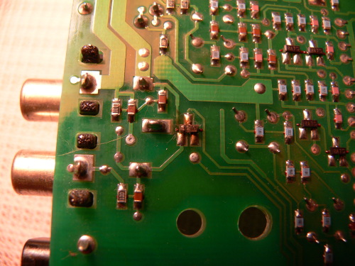 |
|
|
Platinum Member Username: NuckPost Number: 10042 Registered: Dec-04 | A quick sidebar here. Mark, I have not followed this thread for a long time because it does not affect me. I have read the last pages, and I must say, I am impressed with your knowledge and ability to pass the information along. You are truly a boon to the people that you help, and a real champ for the people that need your brains and heart. Cheers, mate! |
|
|
New member Username: AmoldcPost Number: 8 Registered: Dec-07 | Nuck ... I agree with you... Mark is really a Champ and a very good person by heart... He has a lot of patience and always willing to help... |
|
|
Bronze Member Username: Mr3dzpopWoodstock, Georgia USA Post Number: 70 Registered: May-07 | Garry, OK, first of all that IS D412 and it's associated with your amplifiers. You are going to have to open up the amp portion of the sub and see what damage has been done to the amps themselves. That particular part is a dual diode and it sums the output of the two satellite speakers outputs in the DC and overcurrent detection circuit. You are going to need the schematic information on this one. The only way I can see that part being fried like it is would be if the amps failed. Email me and I will get the information to you. That above may not be the only problem you have but it's the most immediate. |
|
|
New member Username: ChiwizPhillipston, MA USA Post Number: 2 Registered: Mar-08 | Mark!!!! I have read with interest all the posts on Bose subwoofers and think mine is a bit different, or at least don't think I saw the complete answer posted... 1) My Sub doesn't work, doesn't power on at all, but all my satellite speakers function when plugged in thru the Sub. 2)The Sub lived next to a baseboard heating panel for quite a while and the black vinyl is peeling off, so maybe extreme heat has something to do with it? 3) I can't get the case off. I remove 2 (that's all I can see) screws and the Bass and LFE knobs, but the plastic case won't budge. I am reluctant to pry too hard with my screwdriver. It looks like it should just slide off, but it won't. From other posts it could be a fuse, a resistor, or a crystal, but I am confused as to which is most likely with my system. Thank you SO MUCH in advance for your expertise. -David |
|
|
New member Username: ChiwizPhillipston, MA USA Post Number: 3 Registered: Mar-08 | Oh! BTW, it is an Acoustimass 15 Subwoofer | |
|
Bronze Member Username: Mr3dzpopWoodstock, Georgia USA Post Number: 71 Registered: May-07 | David, At the top of this discussion thread there are two archived sets of 100 posts. Open the "Active through January 2008" and look for my May 15th post. From there on there are several posts containing exactly what you need to know. The May 15th post explains how to open the cabinet. Being an AM15, your problem is no doubt going to be either a fuse or the resistors. If you still have questions after that then I'll be glad to help. |
|
|
New member Username: Pimpinc333Post Number: 1 Registered: Apr-08 | Hello Mark! I think I have come to the right place for help with my Bose Module :D Ok I bought a set of 5 Double Cubed Bose speakers along with the Bose Acoustimass 25 Module from a buddy. He was unsure if the module worked or not and I'm not sure if it does. Does the Bose Module have any lights on it or such so you know its getting power or does it make a noise when power is going to it? I just might be hooking up the PIN Connecter up wrong and thinking the module doesn't work. I also opened it up to checkthe fuse and it was still intact and measured perfectly. I am trying to hook it up to a Onkyo TX-SR304s Receiver in case you were wondering. Any help with your expertise would be greatly appreciated. Thanks Mark! :D Chris |
|
|
Bronze Member Username: Mr3dzpopWoodstock, Georgia USA Post Number: 72 Registered: May-07 | Well Chris, you have a dilemma. The AM25 may be an AM25 or an AM25 series II. In either case trying to hook it up to an Onkyo or any other receiver is going to present problems. Normally this series of subwoofers are combined with either a CD5V, CD5V2, or a CD20. Any of those consoles can supply the turn-on voltage and the digital data to control both the configuration and the volume levels in the sub. I need to know more about what and how you're trying to hook this thing up to the receiver. Mark B. |
|
|
New member Username: Pimpinc333Post Number: 2 Registered: Apr-08 | Reply to Mark, It is a AM25 Series II BTW. I am actually unsure on how to even hook this thing up. I just want to replace my Pioneer sub with this Bose Module to match my Bose Speakers. I have the Power Cable, Data Cable ( PIN Cable ). My old Pioneer powered sub hooked up to my receiver by a simple one cable ( Like a Video Composite cable buyt only purple ). So I really have no idea how to even start to hook it up. On the end of the PIN cable there is White and Red Audio Connections and what seems like headphone jack type connector. There is a female plug that looks like you can plug a Single Composite cable in. I have no idea how to hook this thing up ( First time I never knew how to hook something up ) If you have any ideas please let me know. Thanks Mark! PS Here is a picture of the back of my Onkyo receiver I own. This may help? http://www.circuitcity.com/ssm/Onkyo-TX-SR304-5-1-Home-Theater-Receiver-TX-SR304 /sem/rpsm/oid/178237/rpem/ccd/productDetail.do |
|
|
New member Username: Bailey58Post Number: 1 Registered: Apr-08 | Hello Mark and Group, Just wanted to post a thank you to all of you and especially to Mark for the many useful posts on this thread. I have 4 Bose lifestyle systems patched together over the years from old systems plus ebay finds plus Bose purchases. Reading these posts has helped me fix 2 subs that have been gathering dust in my garage. You are providing a great service! |
|
|
Bronze Member Username: Mr3dzpopWoodstock, Georgia USA Post Number: 73 Registered: May-07 | Chris, The picture of the Onkyo is of no help to me or you. Virtually all surround receivers have a LFE (LowFrequency) or subwoofer output and it's a low level signal. The AM25 II derives the bass from a combination of LFE content in the main channels and the rest of the audio content is processed to facilitate the front, rear and center channels. Again, the problem you're facing is configuring the sub to do what you want it to do. One of the normally associated consoles supplies this configuration data (as well as volume data) via the remote control supplied with the console. In some older model AM series subwoofers there was a way you could "cheat" the sub and put it into a test mode that would enable all the channels. The AM25II does not operate the same way. Although there are elaborate procedures for testing the unit via a computer and RS232 port, there is no way to operate the system normally. I hate to be the bearer of bad news but what you're trying to do is extremely involved and difficult for even a well versed audio electronics person. Your best bet is to get on ebay and try to find a console to use with it. You can still use your Onkyo for signal source through the Aux jacks on the console but you really need it to perform the control functions necessary. Sorry I could not be of more assistance. |
|
|
New member Username: Pimpinc333Post Number: 3 Registered: Apr-08 | So you basically cannot use the Bose AMII as a Subwoofer replacment, unless you have a bose console? If that is what your saying then I'll just forget about it :D Thanks for all of your help Mark :D |
|
|
Bronze Member Username: Mr3dzpopWoodstock, Georgia USA Post Number: 74 Registered: May-07 | Chris, Yes, unfortunately the console is a virtual MUST! I can tell you that to my knowledge, no one has ever sucessfully converted an AM25II to be compatible with a non-Bose receiver. |
|
|
New member Username: Dan_lPost Number: 1 Registered: Apr-08 | Hello all, I received a non-working lifestyle 12 series 1 system free-b. There is no display, the CD does not spin, no pop/switching sounds from the sub, pretty much DOA. I have --12vdc on the marked pad and 8vcd and 5vd on there respective pins of VR2 and VR3. I'm stuck from there, so I'm looking for a schematic. I'm assuming that the base unit would spin the CD and or light the display even if the "common" fuse problem in the sub was blow? Thanks, Dan |
|
|
New member Username: David_lCa US Post Number: 1 Registered: Apr-08 | Hey Mark You appear to be my only hope. I have an Acoustimass powered speaker system. It has worked great for 17 years. Yesterday the left speaker quit. I checked the reciever, the output cord, the speaker wires, and the speakers. Can you give me an idea where to start in the bass box and some schematics if you have them? Thanks for your help. David |
|
|
Bronze Member Username: Mr3dzpopWoodstock, Georgia USA Post Number: 75 Registered: May-07 | Well first of all David, in those 17 years did you happen to notice if there was a model number on the subwoofer? There's about 'eleventeen dozen' Bose subwoofers out there and I need to know what we're dealing with. Get me a model number and I'm sure we can sort out the problem. Mark |
|
|
New member Username: ChiwizPhillipston, MA USA Post Number: 4 Registered: Mar-08 | Mark, Thank you so much for your help. I will open the thread and see what happens from there. I appreciate your being here. You are a gift. Thanks again | |
|
New member Username: MadtechLawrenceville, Ga Usa Post Number: 1 Registered: Apr-08 | Mark, I have read the archive and the current year's posts and I can really appreciate the knowledge and patience you continue to exhibit. My question is about a Lifestyle Model 5 music center mfg 1995. It has a hum/distortion present in the audio output whenever the cd is accessing the disk and intermittently as disk plays like a transistor breaking down. R604,d605 have signs of heat stress. Bad cd motor/driver or bad optical p/u? or ????Thanks again for giving so much of your time. | |
|
Bronze Member Username: Mr3dzpopWoodstock, Georgia USA Post Number: 76 Registered: May-07 | Alfred, Forget about R604 and D605. Those two components make up a zener referenced 12v supply for the motors. They always look "cooked" mainly because they are. Your problem is more than likely the filter caps in the power supply. When the CD player is actively using it's motors then the load on the supply increases and without adequate filtering you end up with ripple in the supplies. This in turn will manifest as 60Hz hum or distortion in the output. I will give you a list of caps to change in the power supply, the schematics and the board layouts so you can find your way around in there. From the sound of the symptoms and your reference to R604, you have an older model CD5V and not a series 2. You can verify that by looking on the bottom of the console and if there is no "V2" then it's a CD5V. Email me and I will get those items to you post haste. |
|
|
New member Username: MadtechLawrenceville, Ga Usa Post Number: 2 Registered: Apr-08 | Mark, Thanks for your response. I checked and there is no V2 on the bottom of the console. I would definitely appreciate the schematics and layout and parts list you mentioned in order to attempt a repair of this unit. Again, thanks. |
|
|
New member Username: KamagongManilaPhilippines Post Number: 5 Registered: Aug-07 | Hello & Hi, I'm totally frustrated with the BOSE behavior, after extensive search which includes your help, I concluded to call up BOSE and order my parts, resulting in a cold shower by the BOSE people, they just told me on a quite snobbish way that they do not accept any orders for replacement parts. Hope there is someone out there who can help, I need parts for,... Bose 301 Series IV & Acoustimass 10 Series II Tweeter speaker gasket backed part number 181862-SP or 266162 Fuse "lamp, green dot" part number 141989 Anyone who knows where I can buy or find those parts or any other replacement parts, hope someone can help me out here, this problem runs already for the last 10 months and I'm just looking forward to enjoy my sound system again. Thanks John |
|
|
New member Username: AnchonchoLake Forest, California USA Post Number: 1 Registered: May-08 | Hello to all: I see that you guys are really knowledgeable in the Bose Stereo Systems. I have a problem with my Lifestyle 5 Series. On the Subwoofer only the Blue Left and Blue Right speaker works. The Blue Center and the two orange sound outputs don't give any sound. Do you guys think is the remote control (which I press all the bottoms and it doesn't do anything) or u guys thing is the subwoofer that is bad? I'd appreciate any help. Thanks to all! } |
|
|
Bronze Member Username: Mr3dzpopWoodstock, Georgia USA Post Number: 77 Registered: May-07 | Adrian, There is nothing wrong with either the remote control or the subwoofer. Somehow you've gotten the sub out in la-la land and it needs to be reset. Follow these instructions below to clear up the mess. Use the remote for this procedure. "To restore all factory default settings, turn power off then on, press and hold (aproximately 8-10 seconds) the SURROUND (5-speaker) button until you hear the 3-chime confirmation tone, then press and hold the STEREO+CENTER (3-speaker) button until you hear the 3-chime confirmation tone." This will clear up any problems you were having. |
|
|
Bronze Member Username: Mr3dzpopWoodstock, Georgia USA Post Number: 78 Registered: May-07 | John, I can empathize with your frustration but don't give up hope. The lamps are available from: Audio Lab of Ga 3611 Clearview Place Doraville, GA 30340 They can be ordered online using the Bose part number 141989. http://audiolabga.com/ And since they carry speakers they may also be able to find what you need to replace that defective tweeter. sales@audiolabga.com 770-455-0571 |
|
|
New member Username: Peun55Post Number: 1 Registered: May-08 | Hi Mark, I am in Thailand. I have some problems with my 4 Years of Bose LS 28 Series II. The problem are no any light and any letter on my center media for a month and now my bass module Not working for a week so that I am here. I try to find the information on the internet for a time and no one can help me. * Could you please send me the prints and the manual for the Bose LS28 Series II sub and media center ? My email address is peun_t5@hotmail.com Although, I not have skill to repair thing like this. I am marketer, not engineer. But I can hand the print and manual to electronic appliances repairer. I know the shop and I believe that they don't know mush about Bose Lifestyle system. So, I will provide the print and manual to them to check it for me. Thank you so much | |
|
New member Username: EbissoliJersey City, NJ USA Post Number: 1 Registered: May-08 | Hello ! I have a Bose Lifestyle 35 and just moved to NJ. After 2-3 days the power of bass black box shuts off and does not go back on. Took twice to Bose repair and as soon as they turn it on, works beautiful. But, when I bring back home, after another 2-3 days it shuts off again and there is no way I can turn it on. the media center is on but not the bass box, so no sound on the speackers. So, for the reapir center my system has no problem at all. It is weird that I can only make it work again when I take out of my condo area and then 2-3 days only of hapiness...any ideas? thanks !!! | |
|
Bronze Member Username: Mr3dzpopWoodstock, Georgia USA Post Number: 79 Registered: May-07 | Eduardo, I wonder if Bose duplicated your situation? I would bet that if you were to take the sub out of the system for a couple of days and then reinstall, it would do the same thing it does at the Bose service facility, it would work fine. BUT... do they leave it connected to a system for 3 days as you do? I doubt it. Not to cast aspersions at Bose, it simply isn't practical to have a system tied up in a test configuration for that period of time. I would suggest that you do some diagnostics of your own to narrow down the problem to either a LS48 (sub) or AV38 (media center) source. I am including a quoted paragraph regarding the use of the two LEDs present on the subwoofer. They are barley visible and are located where you plug the RJ45 cable into the subwoofer. copy and print the paragraph, monitor your sub box and the status of those two LEDs when the system is working and again after it fails. You should be able to narrow the search for the problem source. It is entirely possible there is nothing wrong with the sub and a communications issue is at the forefront. "The amber and green LEDs on the DSP board serve to provide a wealth of information about the status and operation of the DSP board. The following is a summary of the various possible states of the LEDs and a functional description of the state(s) represented. • Green LED: The green LED serves a dual purpose: general system health and serial data received. The green LED will blink once per second with a 50% duty cycle (i.e. on for ½ second, off for ½ second) if the system booted and is running normally. If the unit is in the SmartSpeaker "Off" condition, the green LED will blink briefly (approx. 0.1s ON time) once every 5 seconds. • The green LED will also toggle whenever a serial data byte is received. This will interrupt the normal 1 second blink rate. The green LED blinking faster than 1 Hz usually indicates that it is receiving serial communications. • Amber LED: The amber LED serves to signal 3 conditions: power applied/boot status, S/PDIF status and clipping status. When power is first applied the amber LED will light briefly. If the PROM FLASH checksum is incorrect or hardware does not pass power-on self test, the green LED and amber LED will alternately blink at approximately a 5 Hz rate. If the green LED is blinking at its normal, 1 Hz rate, a blinking, 1Hz amber light indicates that there is no valid S/PDIF signal present: If the amber LED is off while the green LED is blinking normally, then valid S/PDIF is present and being received. Finally, the amber LED will briefly blink (in this case, only when valid S/PDIF is present) when the satellite amps are clipping. This should only occur when playing the system at very high levels." |
|
|
Bronze Member Username: Mr3dzpopWoodstock, Georgia USA Post Number: 80 Registered: May-07 | peun55, Your request for info has been done, should be on its way or there by now. The "no lights, no letters" problem you are having is probably as simple as the ribbon cable coming loose inside the AV18 media center. Very common occurance! I just have to throw this in... this sentence is priceless!!! "I believe that they don't know mush about Bose Lifestyle system." Not many people do as I am finding out. |
|
|
New member Username: EbissoliJersey City, NJ USA Post Number: 2 Registered: May-08 | Thanks Mark. when the systems works, the led on the subwoofer blinks green. when you turn off the unit, blinks between green and amber. When it shuts off by itself, there is no led on at all, giving the impression that the subwoofer is getting no power at all. best. Eduardo | |
|
New member Username: OrbRotorua, North Island New zealand Post Number: 1 Registered: May-08 | Hi I have bose system 20. the fuse R437 has blown on the circuit board that has the connectors on in the sub woofer unit. can anyone tell me the Ohms please. Also i have a CD stuck in the control unit how do you actually get into the unit..so i can get the cassete out thanks |
|
|
Bronze Member Username: Mr3dzpopWoodstock, Georgia USA Post Number: 81 Registered: May-07 | Bob, If R437 is blown then that is not your only problem with the subwoofer. I am assuming that the subwoofer is either a AM5P or an AM20P. In either case R437 is a 7.5 ohm, 2 watt resistor and in conjuction with the optocoupler and triac, is used to power the system on. I suspect you will find other components in that circuitry that have failed. Merely replacing the resistor will only result in the new one frying also. I need your email address to send the CD20 manual to you. Instructions on how to get into the console are in the manual. As far as the stuck CD is concerned, you will have to get to the mechanism and remove it from the console. I will send you a picture of what you're going to find wrong and how to rectify it. Don't try to get into the console without the manual or your in for some real nightmares. |
|
|
Bronze Member Username: Mr3dzpopWoodstock, Georgia USA Post Number: 82 Registered: May-07 | Eduardo, If there are no LEDs lit when the system isn't working then the problem does lie within the subwoofer. Standby power must be failing at some point. First, to verify that, disconnect the subwoofer from the system and leave only the power cord attached. When you plug the sub in and turn the power switch on, the green LED should begin to flash very slowly even though the console is disconnected. If after a period of time it quits flashing, then the sub has lost internal power. This could be as simple as a bad connection or failure of the SMPS. (Switch mode power supply). Armed with that information, if you choose to take it back to the Bose service facility, then explain to them what is occuring and insist that it DOES indeed have a problem. They'll just have to leave it on until the problem manifests itself. |
|
|
New member Username: KamagongManilaPhilippines Post Number: 6 Registered: Aug-07 | Hi Mark, I truly appreciate your support thru sharing your knowledge with all of the DIY members who experience there share of BOSE problems, also I believe the BOSE people in Framingham could learn what real service, hospitality and helping out people means from you. Thanks again Mark. From John,... |
|
|
New member Username: Timestamp1Post Number: 1 Registered: May-08 | Greetings earthlings. Newbie novice with hopefully simple to fix problem here. I have a bose lifestyle system...av28 and PS 28 (no other designation like II or III in the serial number so assume(?) it is series one vintage)? Anyway av unit shows all the lights and says it is doing things like progressing through a CD or DVD, but there is ZERO output from the sub or any or the speakers...zilch, nada. As a test, i did plug in some headphones into the jack on the side of the AV unit, and lo and behold, SOUND ! (at least stereo). I did check the sub power cord and verified 120vac (or thereabouts) was getting to the sub. I thought Mark's earlier post about resetting to factory might help, but alas my remote has only one button for speakers, called 2-3-5, and not a separate 5 button and 3+Stereo, so unable to get any chiming done. Any suggesttions of other things to check on my own? I am NOT the kind of guy who is comfortable with opening up what is sealed. My father instilled this in me when i was young with the familiar quotation "there are only two people who open up the back of a watch....watchmakers and fools". When it comes to thing electronic, I fall into category two. Anyway, any assistance or direction would be appreciated. |
|
|
Bronze Member Username: Mr3dzpopWoodstock, Georgia USA Post Number: 83 Registered: May-07 | Greg, If you will scroll up to my posting of May 9 (to Eduardo) you will find and explanation of the LED indicators present on the PS18,28,48 series subwoofers. Read that post and see if you can narrow down the problem. As a first check, make sure the power switch on the sub is in the 'on' position. I know that may sound overly fundamental but you'd be surprised how many times that simple mistake has been made. If that checks out, make sure you verify that you are addressing zone 1 with your remote and that the cable from the console to the sub is in fact secure in the zone 1 DIN connector and the RJ45 connector at the sub end. The reference to the remote problem was for an entirely different type of system so it wouldn't have done you any good anyway. |
|
|
Bronze Member Username: Mr3dzpopWoodstock, Georgia USA Post Number: 84 Registered: May-07 | Eduardo, I hope you are checking back in here. I re-read your last posting and had missed the reference to the "off" state. You said the green AND amber LEDs were flashing alternately when the system was turned off. That indicates there is a problem with the hardware since this problem only manifests when you either turn the system off or when it shuts down on its own. If it was related to the FLASH ROM programming checksum it would be there all the time. I suspect you have either a power supply, output or protection problem and narrowing that down is going to take someone familiar with how to perform the necessary testing to determine which. Regardless of what the problem is, it still lies within the confines of the sub electronics. |
|
|
New member Username: Timestamp1Post Number: 2 Registered: May-08 | Hi Mark. I'm so new that I did not even know that what applies to LS 38 and 48 systems are common with LS 28.  But, armed with my new knowledge, I went and checked on what those silly little LEDs were doing. First, i verified that the power cord was plugged in and the switch to "on"....Check. Next came the plug into "zone 1"...check. Then, the rj45, check and "clicked". So, on to the LEDs. They are located to the left of the four dip switches, correct? I have to ask, just to be sure, because throughout the entire process, neither light ever lit up. I also saw the post to Eduardo about leaving only the power cord in and watching for the green LED to flash...I tried that, but the LED never did light up. Am i getting closer or farther from figuring this out? But, armed with my new knowledge, I went and checked on what those silly little LEDs were doing. First, i verified that the power cord was plugged in and the switch to "on"....Check. Next came the plug into "zone 1"...check. Then, the rj45, check and "clicked". So, on to the LEDs. They are located to the left of the four dip switches, correct? I have to ask, just to be sure, because throughout the entire process, neither light ever lit up. I also saw the post to Eduardo about leaving only the power cord in and watching for the green LED to flash...I tried that, but the LED never did light up. Am i getting closer or farther from figuring this out?  |
|
|
Bronze Member Username: Mr3dzpopWoodstock, Georgia USA Post Number: 85 Registered: May-07 | Greg, Well, you're closer to figuring out what you need to do next... which is to find someone who can repair the PS28. If there are no LED's lit then the sub is not powering up at all. For whatever the reason, the power supply is not working. This could be due to it's own untimely death or a result of a power surge, i.e. lightning. Normally, if there is an issue with the outputs, the sub will simply stay in a standby mode but with flashing LEDs. In any case I gather that you are not equipped to attempt to service the beast on your own so you have two options. Option one, if you have a local Bose retailer with a service facility then try that or option two, you can deal directly with Bose. Bose charges a flat rate of $165.00 to repair either Lifestyle component be it the DVD console or the subwoofer. You may reach them by using the following email address or phone number: Americas_Field_Service@bose.com or phone 1-800-233-4408 |
|
|
New member Username: EbissoliJersey City, NJ USA Post Number: 3 Registered: May-08 | Tks Mark. | |
|
New member Username: EbissoliJersey City, NJ USA Post Number: 4 Registered: May-08 | Mark, I am trying to run all kind of tests I can. I am not an engineer or an expert, just a regular consumer, so do not understand most of the tech talk. I have moved my DVD players, HD cable box to other positions, turned them off/on, shut off my computer that stays close to the system, etc, trying to see if the bose is conflicting with anything at my house (remember, it just does not work here). My last try (and please do not laugh) I turn the subwoofer upside down and so far it is working (for 4 days !! before after 1 or 2 days it would turned off by itself). This can't be the solution, maybe it is just back working, so will turn it back to its correct position this weekend and evaluate it again. Well I will keep checking and updating this cool and very good Forum. Best. Eduardo |
|
|
New member Username: WadaviesPost Number: 1 Registered: Mar-08 | Hi, I have the chance to buy a Lifestyle Music centre on ebay that comes without a RC-9 remoteas a back up for my sisters Lifestyle 12 system-her cd is skipping for a micro second from time to time(may be a matter of cleaning the laser with iso propyl alcohol) Problem is the music centre has no remote-is it possible to determine the code so it can be inputted into a remote?? Thanks |
|
|
Bronze Member Username: Mr3dzpopWoodstock, Georgia USA Post Number: 86 Registered: May-07 | Warren, The problem with your sisters CD player is no doubt the small gear on the sled motor. That small gear meshes with a larger gear and that in turn moves the sled (the part the laser optics are mounted to). The small gear is a press fit on the motor shaft and over time the pressure of the press fit will cause that gear to split. This widens the teeth where the split occurs and the motor hangs on that spot when that section engages the larger gear. When there is finally enough motor current to overcome the catch, the sled jumps forward and the CD skips. Bottom line, that gear probably needs to be replaced. Now for the matter of the remote. In a word NO! You could encode a remote with the BOSE codes but the CD5V as well as most all BOSE equipment uses an RF (radio frequency) remote and not an infrared emitter type used by most other electronic products. If you've ever noticed, you can control a Bose system from another room in close proximity without needing line-of-sight like IR remotes need. There are no programmable RF remotes that I am aware of. |
|
|
New member Username: WadaviesPost Number: 2 Registered: Mar-08 | Mark, Thank you for your polite and immediate reply-incredible support!! Then were I to buy the Lifestyle 5 Music Centre I cannot expect to work out the remote code-nevertheless hopefully it would work without the RC-9. Caveat Emptor. Can Bose determine the remote code at their side?? Thanks again Mark. |
|
|
New member Username: FrogmouthAustralia Post Number: 1 Registered: May-08 | I have an Accountimass 30 Series II from a Lifestyle 50 system. I have just had it repaired for a blown fuse and when I switched it on for the first time I seem to have blown the fuse again. Rather than take it back to the repairer, who seems to take for ever, I would like to check it out for myself but do not know how to get the back off. Can someone give me a few clues as to how to remove the back? Thanks |
|
|
New member Username: GuggiePost Number: 3 Registered: Mar-08 | Mark, First, your help here is greatly appreciated as others have repeatedly said. The fluorescent display on my Lifestyle system continues to work well after replacing various electrolytic caps per your suggestion. An engineering buddy of mine tested the ones I removed and found one bad in the bunch. "One 100uf cap failed the ESR test with excessive reactance at 100Khz" is what he said. I replaced a similar gear as you mention above on a motor that changes the CDs 2 years ago after I did my own diagnosis and pleaded with Bose to send me one. In anticipation of this happening again, have you found an after market source for this gear? maybe in metal like from a hobby store for radio control planes or cars, etc? |
|
|
New member Username: Musicologist1964Post Number: 3 Registered: Apr-08 | Hi, I had a similar problem with the small gear on the sled motor. After disassembling the music centre, I found, like you, that the plastic gear had split radially under the pressure of having been forced on the spindle of the worm gear, widening the gap between two adjacent teeth and causing CD playback to stall every now and then. I fixed the problem as follows. I removed the plastic gear completely from the music centre and glued it back together with supa glue so it was back to its normal dimensions. I then used a small rattail file to open up the bore of the plastic gear until it could slide on and off the spindle of the worm gear. That is, the plastic gear was no longer under pressure when on the worm gear. I then cleaned the spindle of the worm gear spindle thoroughly and supa glued the plastic gear onto it. Since then, my CD hasn't missed a beat. Hope this helps, Garry |
|
|
Bronze Member Username: Mr3dzpopWoodstock, Georgia USA Post Number: 87 Registered: May-07 | Warren, Although the CD5 will work with the sub without a remote you will not be able to change speaker modes, mute or remotely operate the volume. I looked at Ebay and there are 4 RC-9's there for varying prices from a buy-it-now for $99 to one with a high bid so far of $20. You may want to persue that avenue. A Bose without a remote is a pain in the tush. |
|
|
Bronze Member Username: Mr3dzpopWoodstock, Georgia USA Post Number: 88 Registered: May-07 | Ernie, I am attaching an excerpt from the AM25II manaul on how to get inside the subwoofer. The AM30II is the same thing so this should help you with the puzzle box. 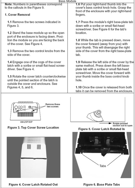 |
|
|
Bronze Member Username: Mr3dzpopWoodstock, Georgia USA Post Number: 89 Registered: May-07 | Ernie, As an aside, I can think of no tangible reason why you should blow a fuse when powering up the system unless there is a shorted speaker wire to any of the cubes or the internal wiring to the bass speakers. |
|
|
Bronze Member Username: Mr3dzpopWoodstock, Georgia USA Post Number: 90 Registered: May-07 | Doug, No I never looked for an after market source for the gear because the mechanism used for the Bose single CD players is the same part Yamaha uses in many of their CD players. I simply ordered them a dozen at a time from Yamaha. Somewhere in this myriad of parts I've accrued, I still have some. |
|
|
New member Username: WadaviesPost Number: 3 Registered: Mar-08 | Mark, If you were able to locate two of the small gears for the sled motor I would be very pleased to compensate you by way of a US dollar check or whatever-postage to Sydney Australia etc. Is there a special trick to remove the CD cover from the single cd player unit-I poked around and was able to uncover the main board but didnt want to force the cd cover unneccasarily. Thanks again-interesting to see other people have expereinced and resolved the same small gear problem |
|
|
Bronze Member Username: Mr3dzpopWoodstock, Georgia USA Post Number: 91 Registered: May-07 | Warren, If you got the other half off the console then you may have broken the little tabs in the back that hold it in. No big deal since the screws are really what secures the top to the bottom. If you will look on the back side (where the connectors are) below where you removed the screws holding the top on, you will see two small trapezoid holes about 1/8" to 1/4". Insert a small flathead screwdriver in one of the holes and gently push the snap lock back. Lift up on the side where you inserted the screwdriver until it moves up a bit and then do the same to the other hole. The CD cover, like the other half, pivots on the front. As I said earlier, if you break the tabs don't sweat it. When you finally get access to the CD mech, on the right side you will see the gears in question. There are actually 3 gears and not two. (Again I made my statements from memory and was wrong) The two large gears simply snap onto their respective shafts and it's a simple matter to grasp the top of the furthest gear from the motor and pull it off. Once that's removed, push the laser assembly back out of the way and remove the second large gear. You can then pull the little gear off the motor. If it's indeed split it will slide off the motor shaft with relative ease. If it's not broken then it would have to be pried off with a small screwdriver placed between it and the motor. Of course if it's not split then leave it alone. Duh! Oh, and while you're in there, carefully clean the lens of the laser assembly. You may use a Q-tip with isopropyl alcohol or even a drop of window cleaner. Just make sure you get all of the junk off the lens. DON'T USE ANY OTHER SOLVENT!! The lens is plastic and some solvents will destroy it. Email me with your Australia address and I will mail a couple of gears to you... when I can find them. I just went and looked and found one but I know I have more somewhere. I'll do some digging tomorrow and see if I can locate the others. I tried to attach the gear to this posting but for some reason it just won't stick. Hmmm go figure 8^) |
|
|
New member Username: GuggiePost Number: 4 Registered: Mar-08 | "Email me with your Australia address and I will mail a couple of gears to you" OK, now that goes beyond the call of duty. That deserves some cool thing sent from Australia! |
|
|
New member Username: FrogmouthAustralia Post Number: 2 Registered: May-08 | Mark Thanks ever so much for the instructions - I have removed the cover successfully and the fuse is blown. I suspect you may be right about a shorted speaker wire to one of the cubes. The repairer assured me that he had the accoustimass running in the workshop without problems so that would elimate an internal wiring problem to the base speakers. It was when I connected it into my cube speakers and switched it on for the first time that it blew. I have the speaker wires running through the ceiling and as we live in the bush we occasionally get the odd bush rat in the ceiling - they are known to have an appetite for plastic. Could I also get a blown fuse if the audio input cable from the multi-room interface to the accoustimass was shorted through a rat chomping into it? Can you please confirm that a 1.6A 250V slow blow fuse is the correct fuse to use? Thanks. |
|
|
New member Username: WadaviesPost Number: 4 Registered: Mar-08 | Mark, Thanks for all of the above-so far in my experimentation I havent broken any of the snap locks-so here goes. email address is wadavies@bigpond.net.au-please enclose your physical mail address as I would like to respond. unbelievably but fortuitously my own Lifestle 12 has started showing signs of small gear slippage-thus the request for two small gears. Look forward to your response so as to initiate my repairs. Very much appreciated Warren Davies |
|
|
Bronze Member Username: Mr3dzpopWoodstock, Georgia USA Post Number: 92 Registered: May-07 | Ernie, No, you can't get a blown fuse from the MRI-AM30PII cable connection. That cable is carrying low level audio, digital and a 10 volt turn-on signal that is supplied by the MRI. A chewed cable might result in loss of control of an attached sub system or loss of an audio channel but that's it. Yes, the 1.6A 250V slo-blo is the correct fuse for your version of the AM30PII. |
|
|
New member Username: DeancPost Number: 1 Registered: May-08 | I've got a Lifestyle 35 that I haven't used in years. Well, I'm not getting any audio. I've looked through this thread and tried looking for LEDs to see if I could diagnose without ripping it apart, but there are none. I've tried a known good power cord and a known good wall socket, too. I've not seen anything specific to the PS48 Acoustimass Module in this thread or the archives so I'm hoping someone can offer some unit specific info. Thanks, Dean. |
|
|
Bronze Member Username: Mr3dzpopWoodstock, Georgia USA Post Number: 93 Registered: May-07 | Dean, The PS48 Acoustimass Module is the same as the module with the Lifestyle 18 and 28. The only difference is the package. The PS48 system uses the Jewel cubes, the PS28 uses the double regular cubes and the PS18 uses single cube speakers. That being said anything applicable to the PS18 is applicable to your PS48. The LEDs in question are very small and are barely visable in the sub where the RJ45 cable attaches to the sub. If you look closely just to the left of the RJ45 input you will see a gang of 4 micro switches (Red housing, white switch actuators) and to the left of that are the two LEDs. One is green and the other is amber (yellow if you ask me). When you plug the bass module in and turn the power switch on (console doesn't need to be hooked up) the green LED should begin flashing. If you will look at my post number 79 on May 9 there is an excerpt from the troubleshooting guide which explains the functions of the LEDs. Use this to do a primary diagnosis of your system. If you will email me I will see that you get the necessary information that may help you further determine what is ailing your system. |
|
|
New member Username: DeancPost Number: 2 Registered: May-08 | I found the LEDs. Do the speakers need to be plugged in or can they be left unplugged like the console? I'm not getting any action on either LED, but I do think I see a spark when I use the toggle switch and I don't think that's a good thing. Dean. |
|
|
Bronze Member Username: Mr3dzpopWoodstock, Georgia USA Post Number: 94 Registered: May-07 | Dean, No the speakers do not have to be plugged in. When you apply power to the sub is goes into what is termed by Bose as the "SmartSpeaker" off state. The power supply is still active in this state but operating at very low current. It does this because the sub uses digital information sent from the console to activate all the electronics within the sub confines. Without an active power supply to power the microprocessor and monitor the RJ45 input you would not be able put the sub into its "on" state. No blinky LEDs, no power from the sub. I suspect there is something wrong with the SMPS. (Switch Mode Power supply) I have sent you the documentation for the sub but unless you're knowlegeable and reasonably adept at electronics and have access to necessary test equipment, it will be virtually impossible for you to troubleshoot and repair this by yourself. |
|
|
New member Username: DeancPost Number: 3 Registered: May-08 | I got ambitious and took it apart. There's juice flowing, so I tested the fuse and it's fine. Does anyone sell replacement 268573-001 assemblies or should I bring it to an electronics junkie I know to replace the switch? Thanks, Dean. |
|
|
New member Username: DeancPost Number: 4 Registered: May-08 | Yeah, it isn't the switch. It sounds like you're right about the power supply, Mark. Thanks for your help but this is way beyond my abilities and living in a small town means that there are no professional electronics shops around. A hobbyist to replace a switch is one thing but complete board diagnostics is entirely another. Is there a market for these things, 'cause I'm sure that I can't afford to get it fixed? Dean. |
|
|
Bronze Member Username: Mr3dzpopWoodstock, Georgia USA Post Number: 95 Registered: May-07 | Dean, Bose will repair the sub for $165.00 flat rate. That means replacing anything and everything it needs, bringing it up to specs and installing the most recent firmware. I don't know where you're located but you're right in assuming that a mom & pop "all things electrical" shop will not be able to tackle that thing. If you should choose to go that route then here is some contact information for Bose. Americas_Field_Service@bose.com or 1-800-233-4408 If you do decide to go the Bose route then it might be worth asking them if they could also install the latest firmware updates for the console while they're at it. It's also worth noting that you can remove the entire sub module electronics and send just that part and not have to package up the entire subwoofer. That would certainly save on shipping costs. |
|
|
New member Username: DeancPost Number: 5 Registered: May-08 | Thanks Mark. I really do appreciate your taking the time to help out as much as you do. Dean. |
|
|
Bronze Member Username: Mr3dzpopWoodstock, Georgia USA Post Number: 96 Registered: May-07 | Dean, I did some further checking and according to Bose's "FLAT RATE" sheet, they will do both parts, console and/or subwoofer for the $165.00 all inclusive. That may not be such a bad deal to get the system completely overhauled and guaranteed for a year. (I think they give a one year warranty on refurbished systems) |
|
|
New member Username: Gonzilla5Post Number: 1 Registered: May-08 | Hello Mark. I'm a newbie to this post but your knowledge has already helped me. I recently bought a bose lifestyle 800 system on ebay. My problem is that it's missing the audio input cable. I was wondering if you have a diagram of the pins. It's an acoustimass 800 powered sub. Your help will be greatly appreciated and thank you for your time. | |
|
Bronze Member Username: Mr3dzpopWoodstock, Georgia USA Post Number: 97 Registered: May-07 | Hector, I'm attaching a diagram to the bottom of this for clarification. You will need a pair of shielded phono cables for the left and right audio inputs and a stereo 3.5mm phone plug and 2 conductor shielded cable for the control/data cable. The tip of the phone plug will connect to pin 12 on the AM800P din plug, the ring of the phone plug to pin 7, and the shaft (shield) connects to pin 3. For the audio cables, left signal to pin 9, right signal to pin 1 and both shields to pin 5. Also jumper pins 2,3,6 and 10 together. They are all ground but do not connect them to pin 5, leave that connected to the signal ground only. The other pins on the AM800P connector are not used by the CD5V2 which I assume you are controlling this with. 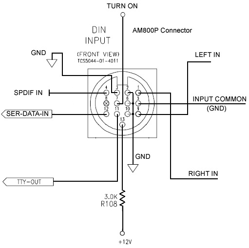 |
|
|
New member Username: FrogmouthAustralia Post Number: 3 Registered: May-08 | Mark I now have my Lifestyle 50 System up and running. I couldn't get a 1.6A slow-blow and had to settle for a 1.5A slow-blow which, to date, is still working. I'm not sure what caused the blown fuse - the fuse I took out had 1.6A 250V on one end and GTE and various approval marks on the other end. My knowledge of fuse identification is scant so I have no idea as to whether it was a slow-blow or fast-blow. I assume it maybe was a fast-blow as the system is now working with the 1.5A slow-blow. Thanks ever so much for the help you gave me - I really appreciate it. |
|
|
New member Username: Chilton88Post Number: 1 Registered: May-08 | "OK Matt, here's the scoop. On the sub side the pinout of the 5 pin din connector is as follows. Pin 1: 12V to power sub. Connect to the tip of the 3.5mm plug. Pin 2: Common for both right and left channel (-) pin 3: Left signal (+) to tip of left RCA plug. Pin 4: Chassis ground. Connect to shaft of 3.5mm plug. Pin 5: Right signal (+) to tip of right RCA plug. Do not connect the common for the two signals to ground in the cable. Use shielded wire for the signal connections and the 12V line. Good luck!" Hello Mr. Burgess, I was just wondering if the 12V need to be connected to anything on the DIN. I want to connect this subwoofer straight to the L and R RCA to a Non-Bose CD player. If I have to connect the 12V to something, is it supposed to be a 12V powersource? Thanks in advance} |
|
|
Bronze Member Username: Mr3dzpopWoodstock, Georgia USA Post Number: 98 Registered: May-07 | Jon, Not to rain on your parade but just exactly which model Bose subwoofer are you trying to connect up here? The information above was for a AM5P subwoofer and for what you're trying to do here, it's about the only Bose subwoofer that would come close to working correctly. Also, please note that your non-Bose CD player MUST have its own volume control because there isn't one on the above mentioned sub. If you try and run line level signal, the sub would be full blast all the time. The answer to the question about the 10-12V turn-on voltage is Pin 1 of the DIN connector just like it says above. Yes too about the power source. The 10-12v when present on pin 1 of the DIN will cause the subwoofer to power up. Remove the voltage and it will shut down, simple as that. BUT... only if your sub is an AM5P, anything else is going to present problems you won't be able to overcome. |
|
|
New member Username: Chilton88Post Number: 2 Registered: May-08 | I'm sorry Mark, I forgot to mention the model. It is a Bose AM5 subwoofer with satellites. The manual was posted with the string. Thank you for the quick reply Jon |
|
|
Bronze Member Username: Mr3dzpopWoodstock, Georgia USA Post Number: 99 Registered: May-07 | Well Jon, you're in good shape if you have an AM5P. If it's just an AM5 then nothing holds true here. I am assuming though, since you inquired about the DIN connector, that it is indeed the AM5P. (The AM5 has no such connector) I might also mention here that the 10-12V turn-on voltage is NOT an absolute necessity. The AM5P has two power supplies and one is always on when the sub is connected to AC.(Unless it's a 220/240V version which has a power switch that must be on also.) You can either power the sub on using an applied voltage (10-12VDC) to pin 1 of the DIN connector or simply rely on the "Audio Sense" circuitry to power the sub on in the presence of an audio signal. The sub will power down to standby mode after about two minutes of a "no signal" condition. Bottom line is, don't sweat trying to come up with a control supply if you don't already have one ready to go. |
|
|
New member Username: RknottPost Number: 1 Registered: Jun-08 | I have an AM15II that was given to me. However, I am missing both the power cable and the system input cable (the 15 pin cable to the reciever). Does anyone have part numbers for either of these and/or know what the pin outs would be for this 15 pin cable, as I should easily be able to make one if I know what the pin outs are. Thanks in advance for any help you can provide! |
|
|
Bronze Member Username: Mr3dzpopWoodstock, Georgia USA Post Number: 100 Registered: May-07 | Becky, In the following explanation and pinout, (-) will represent the black speaker posts or connections on your receiver and (+) the red posts or speaker connections. As you know, the AM15II is driven directly from your surround (or stereo) receiver speaker outputs with the exception of the LFE (subwoofer) signal which is derived from your subwoofer or LFE phono jack if the receiver is so equipped. The Center Surround connections Pins 7 & 8 should be considered NC (no connection) unless your receiver and the Bose provides an output for this speaker. The speaker outputs from the AM15II are then routed to your existing speakers or to Bose Cube speakers if you have them. The use of the LFE or subwoofer portion of the cable is not essential since the low frequency content of the other channels is summed, filtered and directed to the subwoofer amplifier housed within the cabinet. The normal channels are NOT amplified by the AM15II, only filtered and passed back out of the phono type speaker output jacks. Automatic turn of of the AM15II is accomplished by sensing an active signal on the inputs and the system goes back into standby after several minutes of a "no signal" condition. The main power switch on the Bose must be on of course. Pin 1 Left(-) Pin 2 Left(+) Pin 3 Right(-) Pin 4 Right(+) PIn 5 Center(-) Pin 6 Center(+) Pin 7 Center Surround(-) Pin 8 Center Surround(+) Pin 9 NC Pin 10 Left Surround(-) Pin 11 Left Surround(+) Pin 12 Right Surround(-) Pin 13 Right Surround(+) Pin 14 LFE signal or (+) Pin 15 LFE shield, Ground (-) Please note that all speaker leads are in two wire sets with the exception of LFE which should be a shielded cable terminated at the receiver end with a phono plug. (LFE (+) to the tip and (-) to the shield). If interested the part number for the interface cable is 264822-001 for the black cable and 264822-002 for the same part in white. Hope this helps. MB |
|
|
New member Username: RknottPost Number: 2 Registered: Jun-08 | Mark, Thanks so much, that is exactly what I needed!!! |
|
|
New member Username: Hombreman007Mxico, Chalco Mexico Post Number: 1 Registered: Jun-08 | hi!! I hope you can help me I have a bose ps28, only the box, I mean, whitout the lifestyle module, I would like the pinout to power on, it has rj 45 input, any help will be greatly appreciated. thanks a lot and greetings from México! |
|
|
Silver Member Username: Mr3dzpopWoodstock, Georgia USA Post Number: 101 Registered: May-07 | Horacio, I hate to be the bearer of bad news but when you turn on the power switch on the sub it's in a standby mode as you can see by the flashing green LED. Power on/off commands, configuration data and audio is supplied to the sub module via the RJ45 input in digital format. Without the console you are unfortunately completely out of luck. |
|
|
New member Username: Hombreman007Mxico, Chalco Mexico Post Number: 2 Registered: Jun-08 | Hi Mark Thank You for your rapid answer, ...well I supouse I will have to buy a console PS28, now I know there is not other way to turn it on, let me tell you I was about to connect 12v on pin 1, just like others models of sub bose I have seen before, fortunately I found this forum, Thanks again Mark and when I get the console I think I will contact you again to solve some others doubds that I may will have about this bose system greetings!! p.s. I live in Mexico, if I have some errors in my writing, pardon me and don´t hesitate to correct me. |
|
|
New member Username: Cella7Post Number: 1 Registered: Jun-08 | I hope I am not repeating a post, but I didn't see this specific problem posted here. I have a Bose Lifestyle 5 system, with a broken CD player. When you power on the system, it makes a clicking noise for about 10-15 seconds. I've removed the unit myself, and believe I've isolated the problem to a small toggle-like switch that has a broken connector. I called Bose to inquire about a replacement CD unit, and was told that they do not sell specific parts but could recondition it for $225. I'd still like to try fixing this myself. So... I was wondering if anyone knew a good source for purchasing replacement parts. Ebay seems to only have complete systems. Thanks! | |
|
Silver Member Username: Mr3dzpopWoodstock, Georgia USA Post Number: 102 Registered: May-07 | Rob, I'm not 100% sure which switch you are referring to but I will take a stab at it and assume it's the home switch on the CD mechanism itself. I will also assume this to be a CD5V CD console. If you will, please describe in as much detail as possible the location of what you perceive to be the problem and if possible provide a picture if you have access to a digital camera. Doesn't need to be in great detail but as they say, a picture is worth a 1000 words. I will check back later for your response. I'm relatively sure I can assist you in getting your CD player going again. Mark B. |
|
|
New member Username: Cella7Des Moines, IA Post Number: 2 Registered: Jun-08 | Mark, Thanks for the offer of help. When the unit is first powered on, the CD mechanism will move to the 'home' position where it then makes the clicking noise as the gears continue to turn. It doesn't seem to register that it has reached this point, even though the toggle switch has been engaged. I looked closely at the switch and it appeared that one of the contacts was broken. I've attached a picture of the part that I unsoldered from the board. My thought is that this is the problem... the CD mechanism never knows that it reaches the home position since the contact is never made. Thoughts? 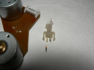 |
|
|
Silver Member Username: Mr3dzpopWoodstock, Georgia USA Post Number: 103 Registered: May-07 | Yep, that'll do it every time. Table of contents of any CD is at the very beginning of the CD (innermost tracks) and it is for this reason that the optical block goes "home" when powered up. Email me directly with a shipping address and I will dig one up for you and ship it. Simply replace the switch and you'll be good to go. Carefully clean the lens while you're at it and check the small drive gear on the sled motor to make sure it's not split. Might as well cover all the bases while your at it. MB. |
|
|
New member Username: Cella7Des Moines, IA Post Number: 3 Registered: Jun-08 | Everything else looks good on it. Thanks for the offer of getting a part to me... that's way above and beyond! Much appreciated! | |
|
New member Username: Retired_bobPost Number: 1 Registered: Jul-08 | Mark, Could you help-me?... I have a system 12 and been following your help you offer others..Mine is a simple question... How do we open the litlle Subwoofer thingy ? soI can look in on the Fuses ? Thanks.. |
Main Forums
Today's Posts- Home Audio Forum
- A/V Receivers Forum
- Amps Forum
- Cassette Forum
- CD Players Forum
- CD Recorders Forum
- DAC & Transports Forum
- DVD-Audio & SACD Forum
- Equalizers Forum
- Integrated Amps Forum
- iPod Docks Forum
- MiniDisc Forum
- Mini Systems Forum
- Digital Music Systems Forum
- Phono Forum
- Preamps Forum
- Speakers Forum
- Subwoofers Forum
- Tuners Forum
- Home Video Forum
- Home Theater Forum
- Car Audio Forum
- Accessories Forum
- All Forum Topics