93 Ford Probe Wiring
|
New member Username: BenjhindPost Number: 1 Registered: Jul-08 | I have a 93 Ford Probe. It came with the premium stereo option which included an amp. When I bought it, one of the audio harnesses was cut. The power side works fine. The other side has the following wires: light blue/black yellow purple/white white/red light blue light green white/orange brown one bare silver wire Do these need to be hooked up to a line level (RCA jack) or a speaker level line on my deck? My understanding is that these wires go to the factory amp which under the rear right speaker. Thanks! |
|
Gold Member Username: Kpa2727Old Bridge, NJ USA ! Post Number: 1409 Registered: May-07 | Typical Ford "Typical" New Radio Pin What It Is In Dash Wire Color Equivalent Wire Color A Right Rear Spkr (-) Blue Purple w/ Black Stripe B Right Rear Spkr (+) White w/ Blue Stripe Purple C Right Front Spkr (-) White Gray w/ Black Stripe D Right Front Spkr (+) Blue w/ White Stripe Gray E Left Rear Spkr (-) Red w/ Blue Stripe Green w/ Black Stripe F Left Rear Spkr (+) White w/ Blue Stripe Green G Left Front Spkr (-) Blue w/ Orange Stripe White w/ Black Stripe H Left Front Spkr (+) Purple White I Amplifier Turn On Do Not Use For This Vehicle J Power Antenna Turn On Do Not Use For This Vehicle K Ground Wire Black Black L Do Not Use For This Vehicle M Dash Light Dimmer Wire Orange (if available) N +12 Volt Ignition Wire Blue w/ Black Stripe Red O Do Not Use For This Vehicle P +12 Volt Battery Wire Blue w/ Red Stripe Yellow NOTE Regarding Ford Wire Colors: Most major auto makers use the same wire colors year after year . However, Ford does not consistently use the same wire colors. Two identical vehicles can have different wire colors depending upon the year of the vehicle where different models may have completely different wire colors from all other Ford vehicles. Ford uses 3 wiring configurations which makes it difficult to accurately show correct radio wire configurations and wire colors. Standard wire harness connectors: this connector design is for basic radios but many times one vehicle model has different wire colors from another vehicle model. Premium or amplified wire harness connectors: these connectors are used with JBL, Mach, and other Ford amplified radio systems. One connector has all wires contained inside a gray data cable and these wires should never be cut. Common ground wiring: Older Ford vehicles used a common ground wiring method or in other words they only used one ground wire for all speakers in the vehicle. This wiring method |
|
New member Username: BenjhindPost Number: 2 Registered: Jul-08 | This is what the cut harness looks like. http://i125.photobucket.com/albums/p48/benjhind/DSC_0068.jpg Pins are as follows (as oriented in the picture in the link): 1 2 3 4 5 6 7 8 1 - light blue 2 - purple/white 3 - brown 4 - white/red 5 - yellow 6 - light blue/black 7 - white/orange 8 - light green one bare silver wire - grounds to outside of case. Where do these wires go? Should they go to a line level input or a speaker level input? |
|
Gold Member Username: Kpa2727Old Bridge, NJ USA ! Post Number: 1414 Registered: May-07 | this might help u better http://www.installdr.com/Harnesses/Ford-Wiring.pdf |
|
New member Username: BenjhindPost Number: 3 Registered: Jul-08 | Thanks Keith! Well, looks like I'm out of luck. At least I still have the connector. It says they should NEVER be cut, and the guy I bought this off of must not have read that. Looks like I'm buying more stuff  |
|
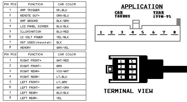
New member Username: BenjhindPost Number: 4 Registered: Jul-08 | FINALLY FREAKING FOUND IT!!!!!!!!! Needs line level input: http://i13.photobucket.com/albums/a267/ender03/Radio%20Install/fordtaurus1.jpg |
|
Gold Member Username: Kpa2727Old Bridge, NJ USA ! Post Number: 1416 Registered: May-07 | ah, nice i hope it all works out for you. |
|
New member Username: BenjhindPost Number: 5 Registered: Jul-08 | Hey Keith, I followed that wiring diagram and it worked out perfectly. I wonder why they say never to cut that cable? It was nice and easy. The only thing is that I have read that if you put speaker-level signals through the amp, you'll damage the amp or the speakers, so anyone wanting to follow this, make sure you use a line-level output (RCA jack style). Thanks for the help Keith. |
|
Gold Member Username: Kpa2727Old Bridge, NJ USA ! Post Number: 1428 Registered: May-07 | np and most of the times all them say never to cut it. cause once you do the pinout location may be different from what was stated. blue migh be pin 1 in a 94 and blue maybe pin 6 in a 97. i'm pretty sure thats the main reason in doing so. |
Main Forums
Today's Posts- Home Audio Forum
- Home Video Forum
- Home Theater Forum
- Car Audio Forum
- Accessories Forum
- All Forum Topics