Help Jtaging a Pansat 3500sd
|
Gold Member Username: JohnnerMiami, Florida Post Number: 1054 Registered: Nov-05 | Any Info appreciated I have the cable (Parallel to 20 pin) but the software I'm using does not appear that is doing anything please help thanks. |
|
Silver Member Username: Cartier1Post Number: 470 Registered: Feb-07 | ask satscanner he is master in fta. |
|
Silver Member Username: Albino_midgetPost Number: 502 Registered: Jul-06 | Used wall and jkeys and it worked. after flashed chip , rebooted the 3500 and it displayed b-80. |
|
Silver Member Username: RunnerguyPluto Post Number: 202 Registered: Sep-06 | C/P from FTA Talk how to jtag for 3500s -------------------------------------------------------------------------------- You can get a jtag cable on Ebay. Pic attached. You can the needed file from FTA Talk or just google "jtag 3500" I opened up my unit and found that the motherboard has the following markings: GSR3500 Rev. D_1 2005.06.01. I found the flash chip and it is a 29LV160CBTC-70. A 2MB flash rom chip. I needed to make a JTAG cable or buy one. Since one is usally in a rush to get their machine back up and running, I decided to build my own cable based on instructions from 'Adversary' in one of his forum posts. Here is what I bought from RadioShack: 5 100Ohm Resistors at $1, A shielded hood fro my DB25 connector at $2.50 and a Sub-DB25 male solder plug for $2. So I spent $5.50 instead of $20 on eBay (plus waiting time). I also grabbed an old 40-wire 40-pin IDE cable. I cut the IDE cable in half length-wise so that I ended up having a 20-pin 20-wire cable. My 3500s already has a 20-pin JTAG header which makes it easier. I understand from other posts that sometimes you will need to solder stuff onto the board... Here is Adversary's pinout: DB25 male connector .........................To Pansat JTAG plug (20 pin header) Pin 2 -------------> 100 ohm resistor ---------------> JTAG Pin 9 Pin 3 -------------> 100 ohm resistor ---------------> JTAG Pin 11 Pin 4 -------------> 100 ohm resistor ---------------> JTAG Pin 13 Pin 5 -------------> 100 ohm resistor ---------------> JTAG Pin 19 Pin 13-------------> 100 ohm resistor ---------------> JTAG Pin 15 Pin 18~25------------------------------------------> Pansat GND (JTAG pin 16 is GND) Apparently this cable also works for other Pansat units. It definitely worked for my 3500S. One thing that is important is to have a maximum distance from DB-25 to JTAG connector of about 12 inches. Don't make your cable longer than this, might cause complications. I spent 1 hour making the cable and then ran the software attached below. Inside WALL.ZIP you will find the "wall" program. It's purpose is not quite clear to me, but it is recommended to have this program running while using the other program called JKEYS. The last file PANSAT3500S_29LV160CBTC-70.ZIP contains a copy of the 2MB flash I used. This flash basically is the BL 1.37 code plus a working channel list for Echo 7 and Echo6.8, also known as 110 and 119. Steps to JTAG. 1. Make the cable. Take care to not have wires touching that are not supposed to, ensure you get the ground pins all connected etc. If you don't know how to solder find someone who can. 2. Leave your receiver off, carefully open it up, don't start touching stuff. If this fails you'll need to send the unit back to Panarex and you don't want them fixing more than needed. --- Before going on --- Disclaimer: I want to state that these instructions here are a documentation of steps I took to fix my machine and I am posting them for anyone who has s similar problem and is willing to risk it. I do not guarantee that this will work for you. I take no resonsibilty for your actions and what happens due to you following this guide. Do this at your own risk. End of Disclaimer --- 3. Plug in your JTAG connector and then carefully connect the DB25 male connector to your parallel port on the back of your computer. I suggest using a real LPT port, not a USB to parallel DB25 converter. You also want to make sure your printer port is configuered to allow bi-directional communication. Mine was set as an ECP... 4. Turn on your receiver. You will see the dreaded b-70 or it might be totally blank if you flashed it with the wrong firmware or the upgrade process was interrupted etc. 5. Run the WALL program and click on "Refresh items" - ignore the "wrong ID" warning - I don't know what that means and as mentioned earlier I am a little sketchy on the purpose of this utility. All I know is it needs to be running. 6. Leave the WALL running and now start the JKEYS program. It will give you some data and might or might not even recognize your unit's flash chip. It should recognize something though. If it states unknown device there might be a problem with your cable. You will not be able to continue until the unit has been correctly identified. Make sure your device is selected on the left side. 7. Click on FLASH PROGRAMMING in the lower right and a new window will open up. You'll get a warning screen which you click through and then you see a similar screen but on the top right there are 3 buttons: ERASE, READ, PROGRAM. 8. On the left side again ensure that JKEYS is correctly recognizing your chip. Numbers should match those of the chip on your board. Click on the ERASE button. This will wipe the machine. (If you were to reboot the machine now, it would seem completely dead - but you aren't gonna do that now.) 9. Once the chip is erased successfully, click on the PROGRAM button and specify the PANSAT3500S... .bin file. This file is 2MB large when unpacked. Let the PC doe it;s thing, you should see a windows that looks like a file download with bytes/seconds etc. Took 2:33 minutes to get done on my machine. 10. Once the firmware was successfully written to the flash chip, close the currently open JKEYS window. You should be on the first JKEY window. If you were to press detect, you should see that the unit is now correctly identified etc. Completely exit the JKEYS application. 11. Close the WALL program and then turn off the receiver and disconnect the unit from your PC. Unplug the JTAG connector and then turn your receiver back on. Careful though, the unit is open. Your unit should show a brief b-70 message, then turn ON and then go to a channel. You're done and the unit is fixed. Possible reasons it didn't fix: Wrong .BIN file - make sure the number on the chip matches the .BIN file. I've also seen a 1 MB file for a different version of flash chip, the BBTC-70. You fried some other part of your board - I've read of some users plugging in the wrong cables in the back which can burn out stuff. That can't be fixed by flashing the firmware. If the above don't apply, try it again. If still no go, you might have to send the unit in. thanks to alex for this nice writting piece. the wall and skymax are in jtag download section. made this exception to have files not in down load section, if you have different chip id? post it up, who knows i maybe able to steal some more Attached Images Pansat-3500-MB.jpg (228.8 KB, 1054 views) Attached Files Pansat Jkeys-2500-2700-3500.zip (134.7 KB, 1373 views) PANSAT3500S_29LV160CBTC-70.zip (450.2 KB, 1141 views) __________________ READ THE RULES [link removed] 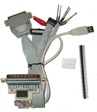 |
|
Gold Member Username: Dude123Post Number: 1036 Registered: Jul-06 | good info zulu |
|
Silver Member Username: RtapFL Post Number: 211 Registered: Jan-07 | heres the procedure i used and worked perfectly. https://www.ecoustics.com/electronics/forum/home-video/335876.html |
|
Silver Member Username: Thechiz2Mars, Ur anis Mine Post Number: 196 Registered: Apr-05 | this is a good giude. very indepth with pics change asters to WWW http://***.future-fta.info/Forums/showthread.php?t=44185 you'll have register |
Main Forums
Today's Posts- Home Audio Forum
- Home Video Forum
- Home Theater Forum
- Car Audio Forum
- Accessories Forum
- All Forum Topics