How Amps Work
|
Gold Member Username: Arande2Rattle your ... Missouri Post Number: 2825 Registered: Dec-06 | Hey. I am trying to understand audio amplifiers better, and am hoping you can help. Clipping will be described as I understand it and if it is incorrect, an explanation of my misunderstanding or a link would be appreciated. Thank you. Clipping... It is a type of distortion where the maximum output of an amplifier is exceeded and the current/voltage flatlines at the maximum output of the amplifier. In a solid-state amp: The clean signal from the source enters the inputs of the amplifier. The power supply has a maximum voltage/current it can supply to the emitter and collector on the transistor. The volume control is turned up until the base of the transistor has a low enough resistance that the full voltage of the power supply is utilized at the peak of the waveform. Now... The volume control is turned up more. The input at the base of the transistor exceeds what is needed to allow the full voltage of the power supply to pass and since no more power is available, the voltage/current running through the transistor from the power supply stays at the maximum until the signal at the base of the transistor goes low enough that the amount of current/voltage that can pass the terminals of the transistor goes below this point. The top of the waveform is "clipped" off as a result. Is this the correct understanding? If not, please help. Thank you. |
|
Platinum Member Username: Jan_b_vigneDallas, TX Post Number: 12727 Registered: May-04 | . I don't understand this part, Andre, " ... the voltage/current running through the transistor from the power supply stays at the maximum until the signal at the base of the transistor goes low enough that the amount of current/voltage that can pass the terminals of the transistor goes below this point." What are you trying to say? What you've posted is not a bad example of what happens at the front of the amplifier which results in clipping. The only significant change I would make is to not even discuss current. The amplifier is running into a constant impedance source when tested. As such current draw is minimal and the amplifier swings voltage more than current when connected to a load resistor. It is only when the load impedance drops that current is a factor and then, as load impedance varies with frequency and each specific speaker load, it is quite unpredictable how much current will be required before the amp runs out of juice. Since watts are made from voltage+current/load, an amplifier can produce lots iof voltage and not clip or it can produce not many amps and still clip. You've also described a very simple set up with what would be considered a passive "pre amp" stage. I'd find a way to not discuss the volume control but think instead of just voltage into the transistor. You've not accounted for drivers or input stages which can cause other problems in the power amplifier. "Clipping" is mostly described as a problem of output stages but any circuit (that feeds a load, i.e., another circuit) can be driven into a clipped status. . |
|
Platinum Member Username: Jan_b_vigneDallas, TX Post Number: 12728 Registered: May-04 | . http://sound.westhost.com/site-map.htm |
|
Gold Member Username: Arande2Rattle your ... Missouri Post Number: 2828 Registered: Dec-06 | "What are you trying to say?" Umm.. how about this wording.. If the voltage at the base passes the point needed to allow the full voltage from the power supply to pass through the transistor, the full voltage of the power supply will pass through until the voltage at the base goes back below the point needed for full voltage from the PS to pass through. That means that the resulting signal output from the transistor will have a flat line where the voltage hits the PS rail level. (that's not exactly true because of many factors like capacitors etc..but it's very basic, as is my knowledge). I understand what you say about current and voltage, and that certainly makes sense. My knowledge is very limited, so thank you for providing a link I can look into which should answer many of my questions. |
|
Platinum Member Username: Jan_b_vigneDallas, TX Post Number: 12729 Registered: May-04 | . I suppose what you've posted is sufficient for now. The transistor obviously tries to accomplish it's task but is faced with a limited voltage supply and insufficient load at the point of clipping. It was, when I was selling, common to discuss clipping/current/load as two people pushing against one another with equal force. As long as the force of the two "loads" remained the same, the situation was stability. If one person suddenly eased up on their side of the load the other fell flat on their face. One problem which I never see addressed when discussing clipping is the the input and output impedance. It may be too complicated to discuss when just trying to understand clipping but they are responsible for determining that mix of voltage and current required by most modern pre amps/drivers on the input side and the loudspeaker load on the output. Most descriptions of how amplifiers operate tend to assume perfect conditions up to the point of clipping. From what I know that isn't exactly how things work in the real world. Another problem which still exists with most descriptions of clipping is talking about the issue as a constant input voltage/frequency derived by way of test equipment outputting a sine wave at a constant voltage rather than the constantly variable input from a music signal when the amplifier is part of a circuit terminated at the speaker load. But you must understand the basic operation before dealing with reality. This will work as long as you get around to reality and do not stop at text book answers. . |
|
Platinum Member Username: Jan_b_vigneDallas, TX Post Number: 12730 Registered: May-04 | . http://lenardaudio.com/education/12_amps.html |
|
Gold Member Username: Arande2Rattle your ... Missouri Post Number: 2830 Registered: Dec-06 | "One problem which I never see addressed when discussing clipping is the the input and output impedance." I remember running across something referring to this (I'll look over it multiple times until I get the info in my head), but the details, I don't. "But you must understand the basic operation before dealing with reality. This will work as long as you get around to reality and do not stop at text book answers." Yes. I am beginning to see there is a whole lot more to it than what is said in most writing. If you design an amplifier (or whatever) based on the textbook, the flaws will be revealed in the way it performs. You can't design a good product without being aware of reality, except by accident. I'm not saying I am aware of reality, though. Not yet, anyway. Hmm.. I always thought that output transistors added voltage and current. Instead, I find that they add current only. I also learned that the stages behind them have to be able to supply enough current to the base of the output transistors to allow this (so that's why just adding more output transistors won't always allow low impedances, as the preceding stages don't have the capability). I wonder if there are any exceptions to this. Another thing..I learned why maximum power output doesn't double when you lower the impedance of the load. In addition to the limits of the components themselves, the power supply voltage will sag more and more as current is drawn (de-regulate) and lower the gains from lower impedances. This explains one of the reasons why my newest receiver has much better low-end response than my old one. The VA rating on the transformer is almost 3x as high and the PS should be stiffer (less sag). The lower impedance at lower frequencies in speakers will require more power and bass usually has the biggest transients and so the quality of the power supply can determine the quality of the bass response. Surely there is a lot more to it than that, though.. I have a lot of reading to do and will probably move on to other things as well (speakers, CD players, circuits in general). Thanks for the help. |
|
Platinum Member Username: NuckPost Number: 10380 Registered: Dec-04 | If you are having fun and learning, Andre, keep it up. |
|
Gold Member Username: Arande2Rattle your ... Missouri Post Number: 2831 Registered: Dec-06 | Uh-huh I am learning... https://www.ecoustics.com/electronics/forum/home-audio/300215.html Especially since my first post: https://www.ecoustics.com/electronics/forum/home-audio/297868.html |
|
Platinum Member Username: Jan_b_vigneDallas, TX Post Number: 12741 Registered: May-04 | . "This explains one of the reasons why my newest receiver has much better low-end response than my old one. The VA rating on the transformer is almost 3x as high and the PS should be stiffer (less sag). The lower impedance at lower frequencies in speakers will require more power and bass usually has the biggest transients and so the quality of the power supply can determine the quality of the bass response. Surely there is a lot more to it than that, though.. " That's why I often suggest you ignore the on-paper specs and buy the heaviest amplifier you can afford. . |
|
Gold Member Username: Arande2Rattle your ... Missouri Post Number: 2832 Registered: Dec-06 | 1) Would the fact that a PS sags with current mean that transients and peaks would be compressed due to a lowering supply voltage as current is drawn? 2) Since I want to learn more about how amplifiers work and also like the idea of a DIY project, what do you think of the idea of building the CMoy headphone amp? http://www.tangentsoft.net/audio/cmoy-tutorial/ It seems like a good idea to me, since audio is the field I plan to enter, I need a headphone amplifier (I have weak portables), and I don't see a reason to spend like $200 on something. |
|
Platinum Member Username: Jan_b_vigneDallas, TX Post Number: 12749 Registered: May-04 | . "1) Would the fact that a PS sags with current mean that transients and peaks would be compressed due to a lowering supply voltage as current is drawn?" Yes, this is the problem with amplifiers that are designed to literally suck current out of the wall socket to hit a big transient peak and then have no storage capacitance left for the next note. Caps can only replenish themself at a given rate and if the music continues to demand more than the caps have the music gets pretty wimpy pretty fast. This is also why some manufacturers prefer multiple small ps caps over several larger caps, the smaller caps can usually restore faster than the large caps. That's not a way around designing a good ps but one method used to work around the real world problems of ps's. I always think building something yourself will teach you more than buying something someone else (or some machine)put togther. This is a fairly simple project that won't teach you alot about amplifiers since the chip is doing all the work but it should give you a sense of how things go together and then you can move on to bigger projects. Sounds like a plan, Andre. . |
|
Silver Member Username: MagfanUSA Post Number: 268 Registered: Oct-07 | Carver Amps, those made after the original Phase Linear efforts used what I think was called a tracking power supply. My Cube, for example doesn't store energy except in the magnetic field of a pretty good sized choke. The idea was to turn the power line on / off in time to the music. The M-400t (mod) was 200x2 and 500 bridged mono. I think the spec was also 250x2 4ohms, so lo impedence drive capability was only so-so. No large conventional caps were used in this circuit. The output end was a more conventional A/B affair with 6 output devices per channel. If your house wiring was sub-par you'd find out when the whole house began flickering in time to the music. |
|
Platinum Member Username: Jan_b_vigneDallas, TX Post Number: 12750 Registered: May-04 | . That and the smell of overheated wires inside your walls. |
|
Silver Member Username: MagfanUSA Post Number: 269 Registered: Oct-07 | So much for tract house wiring. The new 20amp circuit feeding ONLY the amp and sub is a big help. Not a flicker out of anything, even when the A/C comes on. House has no electrical 'ghosts' as a result of this abuse and I've been here 20+ years. The Carver amp had a 15amp fuse 'quick blo' because it needed it. This thing would suck a regular house circuit dry when playing Very loud into lo-impedence speakers. Bob Carver's point was to do away with in-amp storage of power and go right to the 'source'. I just went to my museum for another look . This amp came with the cheesiest speaker wire connectors and what surely must be a 14ga or 16ga hard-wired plug. Fixing both would be on any retrofit list. I know.........why bother? |
|
Silver Member Username: MagfanUSA Post Number: 270 Registered: Oct-07 | One other minor point about amps. The old cube was hard on the power lines, no doubt. That my place didn't burn to the ground might be luck or good /reasonable construction. Just for the exercise, assume a stereo and a listener who likes it loud. You have 2 amps. A conventional PS with large caps for storage and a 2nd amp with NO storage that can turn the wall power on and off in time to the music. Both amps have the same RMS power and same output topology so you can assume similar efficiencies in the 55 to 60% range. Playing a sine wave or white noise, they will draw the same from the power line. With normally dynamic music the conventional amp will have a more even draw, replensihing during lulls and drawing the caps down during peaks. On the other hand, the tracking PS amp will go from very low draw during lulls to huge peaks during cresendos. This is what I saw with the old cube (RIP) when really pushed. The average draw should be the same for both amps, given same RMS power and efficiency. Just extend the regulation model from the amp back to the power it draws from. Same diff, no? |
|
Gold Member Username: Arande2Rattle your ... Missouri Post Number: 2836 Registered: Dec-06 | Leo: I don't understand how the cube was designed inside to do that (no caps, transformer?) On the headphone amp, I am currently selecting the parts I want so that I can order everything at once. If I have any questions, I'll ask here. |
|
Silver Member Username: MagfanUSA Post Number: 271 Registered: Oct-07 | Andre, the Cube uses a choke, kind of a single winding transformer. It would hold 1 cycle of the AC line than 'discharge' it thru the rest of the PS. The cube gave rise to other, more refined efforts by Bob Carver to design a power supply that would track the input signal and provide only that power required at that moment with minimal storage. A choke used in this manner stores a pretty good jolt of juice, when the magnetic field collapses, you get it back as one zap of electricity...at reasonable efficiency. In so doing my cube lasted over 20 years (maybe 25?) was repaired once at power company expense and even drove my MG-1s, built probably late 70's. I suspect but can't prove that a choke will discharge more quickly than a cap, but am NOT SURE. When just sitting there, the amp would emit a Very Low Level 'putting' noise @60hz. The cube is an interesting footnote which probably has little or nothing to do with current amp PS design. Andre, you need to go talk to a power supply geek. Maybe even someone with a schematic of the cube. I only know a few other things for certain, one of which is the darn thing ran fairly cool unless really pushed. I made a 4" box fan and enclosure that sat on the back of the amp and pulled a LOT of air thru it. Under these conditions, it stayed 100% cool to the touch, but in order to cover the fan noise you also had to REALLY play it loud. Thus, my neighbors thought I was deaf. It never occurred to them to question a Deaf Audiophile! |
|
Platinum Member Username: NuckPost Number: 10391 Registered: Dec-04 | Pardon me? |
|
Gold Member Username: Arande2Rattle your ... Missouri Post Number: 2837 Registered: Dec-06 | Interesting....joo crazy, in a good way. The power supply has flaws in the virtual ground circuit that I don't think I would be good enough to change the design myself. However, I may later change it if not satisfied. There is also no DC input jack. On the other side, I have looked into each component carefully and selected the optimum one based on what I want (hand matching high quality resistors for example). Of course, the flaws that cannot be easily fixed (limited knowledge) will be there (Op-amp problems for example). The quality of the work I do will be very important and I must be very careful with how I wire everything. I am sure I will get confused more than once on how to wire it. Again, I'll probably ask here if I run into a problem I think you could help solve. |
|
Platinum Member Username: Jan_b_vigneDallas, TX Post Number: 12752 Registered: May-04 | . I wouldn't worry much about hand picking resistors when the signal eventually runs through an op-amp. There's probably a couple dozen resistors in that IC that you can't hand pick. I know they don't cost much but save your money for when it really counts. |
|
Platinum Member Username: Jan_b_vigneDallas, TX Post Number: 12753 Registered: May-04 | . "There is also no DC input jack." You simply add one. (http://www.tangentsoft.net/audio/cmoy-tutorial/tweaks.html) But the wall wart power supply you would use will introduce high frequency switching noise that won't exist with battery power. Use high amperage rechargeables and forget the DC power supply. Look into a sealed lead acid battery with a floating charger if you want to get fancy, it will make more difference than hand picked resistors. That will make this less than portable though and good rechargeables that you can place in a charger will do all you need for this circuit. . |
|
Silver Member Username: MagfanUSA Post Number: 273 Registered: Oct-07 | Andre, You'll also probably need not 1, but 2 sets of batteries. Plus 2 common and Negative 2 common. this will give you the 2 'rail' voltages of amps. While the following link is for a class'd' amp, the power supply details apply across the board. http://www.irf.com/product-info/audio/classdtutorial.pdf |
|
Gold Member Username: Arande2Rattle your ... Missouri Post Number: 2838 Registered: Dec-06 | Jan: I had not thought about the resistors inside the IC, so I will just buy the number I need and not hand match. Thanks. The tolerances are sufficient anyway. The reason I wasn't going to put a DC power jack in was because I don't want to deal with it right now. It's easy to add one in if I ever feel I need one. I could also have a larger battery pack which I can connect. Either way, it won't be too much trouble. Leo: The reason I am not using 2 sets of batteries is because of the possibility of DC offset if the batteries get uneven in their voltages. The guy on the site says that we want to do it with one voltage source. I was planning on sticking with a resistor divider to do this, even with its flaws. If I do find problems in the future, I will be a little more experienced and could probably change the virtual ground circuit to something that won't unbalance. I have a question. When an OPA is rated for a supply voltage up to ±18v, does that mean each voltage rail can be up to 18v? If so, I could put 35v to the circuit (why I chose 35v capacitors) and have 17.5v voltage rails. Some low efficiency high impedance headphones might need the boost? Thanks for your help guys. If you (still) think I should do something different than I planned, I might look into it more. |
|
Platinum Member Username: Jan_b_vigneDallas, TX Post Number: 12754 Registered: May-04 | . I would assume the 18V you mention is 18V for each side of the + and - rail. That would mean you want 18V total. You do not want to try upping the power by using a higher Voltage than spec'd. |
|
Silver Member Username: MagfanUSA Post Number: 274 Registered: Oct-07 | Andre, Don't worry about DC offset of a pair of battery packs. You'll regulate it to a lower voltage, anyway. If you use the amp enough to get the batteries below the regulated voltage, you have other problems. The IR amp I am trying to get from my company calls for +-25 to 35v. I would get 3x12 (series gel cells) and regulate to somewhat less than 35v. An automotive lead/acid battery when fully charged is way over 12v. In using a battery for this application, always have higher battery voltage and use a regulator to bring it down. This ensures stability. If I wanted +- 18v (36 volts total) I'd be tempted to run 2 sets of 3x6v gel cells in series... Jan @100% with recommendation not NOT over voltage the amp. Read the White Paper I linked and you'll see. For higher power applications, use different spec'd output devices. Jan, just curious, When I brought up batteries in the context of a home system you were not enthused. Maybe that amp I linked...the 25kilo$ 'Emitter' changed your mind? Batteries sure get around the problems associated with amp power supplies, while introducing a few of there own. |
|
Platinum Member Username: NuckPost Number: 10398 Registered: Dec-04 | L/A batteries achive full capacity at 14.8vdc. Low charge is considered to be 9.8vdc. Both useless. |
|
Gold Member Username: Arande2Rattle your ... Missouri Post Number: 2839 Registered: Dec-06 | Jan: If that is so, then why does the guy who made that site talk about using 24v wall supplies or even higher? Leo: Regulation? How do you do that? That just brings me back to using a good virtual ground circuit that won't let the voltage rails deviate away from their intended values. I tried looking at your link, but I don't know where to look. The original Chu Moy design used a single 9v and this guy's tutorial uses 18v because he says the virtual ground might deviate off-center. Does that make sense or am I horribly confused? |
|
Platinum Member Username: Jan_b_vigneDallas, TX Post Number: 12756 Registered: May-04 | . "Jan, just curious, When I brought up batteries in the context of a home system you were not enthused. Maybe that amp I linked...the 25kilo$ 'Emitter' changed your mind?" Sorry, leo, I'm not sure what you're talking about. I barely remember a thread about battery power. I seem to remember some discussion of automotive batteries and lots of gel cells that would add up to the size of a refrigerator. I'm not much on battery powered high wattage power amplifiers and doubt I will ever change my mind on that. For low wattage and pre amps batteries do fine. "Jan: If that is so, then why does the guy who made that site talk about using 24v wall supplies or even higher?" I don't know, Andre. Doesn't he explain why he suggests something? I've not read much of the text and not listened to the tutorials. It's possible he expects the wall wart power supplies to drop to an acceptable working voltage when put under load conditions. A circuit will have an acceptable range of supply Voltage and you can goose a bit more power out of an amplifier by running the input a bit hotter. But why? You'll gain a dB and loose the life and reliability of the circuit. This whole "watts are cheap" mentality that exists puts the emphasis on bulling your way through problems rather than looking for the most "elegant" solution. Forget the watts and SPL's, Andre, and concentrate on the sound and the reliability of having that sound. If you want higher SPL's, buy components that do it without stress, which usually means higher sensitivity in the speakers/headphones and higher impedance in the load. Why didn't amplifiers like the Carver Cube catch on? Because Carver broke the rules just to prove he could not because it sounded the best. No one else builds amplifiers like Bob Carver. Most people - no offense, leo - think that's a good thing. . |
|
Platinum Member Username: Jan_b_vigneDallas, TX Post Number: 12757 Registered: May-04 | . Andre - Just scanning the various linked sections of the article I find the author discussing higher Voltages in several locations so I'm not sure what you're reading and taking away "high supply Voltages should work". There is a section where he discusses splitting the Voltage rails into + and - rails with what would appear to be a separate regulation circuit and using a high Voltage supply (18V X 2 = 36V). But he warns this has dangers and, IMO, the expense and potential danger to the circuit should a part fail don't provide a good enough reason to go this route - at least not as a first build. Maybe I'm missing something because I'm not reading the entire article but I would consider building a simple version of this amplifier and listening to that for awhile. Then, if you wish to tweak this circuit, you can make changes and listen for sould quality improvements made when you make a change. Doing this one change at a time is the proper way to learn what changes when you tweak. Doing more than one thing is not the way to do this upgrade. Not knowing where you started is not the way to learn to tweak. Establish a baseline and then move slowly from there, one thing at a time, so you always know what changes with each step. Remain patient by moving forward slowly and you will gain the most knowledge and the highest benefits from the project. DIY should be a learning process not a "I'm going to build the best the first time out" type of affair. You only slowly move forward with DIY. The only time you should move backwards is to double check the results of what you think happened when you tweaked forward. . |
|
Silver Member Username: MagfanUSA Post Number: 275 Registered: Oct-07 | Actually Jan, the previous discussion centered on class 'd' stuff which makes good use of available power. No offense taken on the Carver stuff. Bob Carver is a Maverick designer, no doubt. I was very happy with my Cube for quite a number of years. He has, however evolved his designs over the years from his earliest Phase Linear efforts thru his current SunFire offerings. In 100 years, Carver will be much more than a footnote, but certainly not a chapter! Andre, to put what Jan said in as few words as possible:: Good Designs evolve. |
|
Gold Member Username: Arande2Rattle your ... Missouri Post Number: 2840 Registered: Dec-06 | Firstly, after looking at the op-amp more closely... Under the title ABSOLUTE MAXIMUM RATINGS (take note that they are ABSOLUTE MAXIMUM): Supply Voltage, V+ to V-, 36v Input Voltage, =0.7v to +0.7v Output Short Circuit, Continuous And then the short circuit current is 80ma rail-to-rail. A diagram shows minimum supply voltage V+ to V-, 5v. Typical says 30v...and then maximum says 36v. I can gather from this that 30v rail-to-rail is the max you can safely do and between 30v and 36v is a safety zone in case your supply is a little higher than it is spec'd. Anyway though.. I will keep the normal dual 9v batteries in his schematic, though. He did say that it's better to keep the supply voltage higher (virtual ground page) and that's why his schematic has 2x9v instead of 1. Ok.. A basic design will be fine. I did change some things, though. If you have any objections to what I list now, tell me: -LED/Resistor, I chose a 'soft orange' LED, then used the formula to arrive at a resistor value of 8.66k (default 10k). -Virtual Ground Resistors, I lowered them from his (4.67k) to 4.42k in hopes of helping keep it closer to equal rail voltages. If you really advise that I just go with 4.67k, then I will. -Power Supply Caps, All I did here was change to a higher grade of capacitor (I mean..what's 50 cents difference?) because of better specs. Input Caps..I used the same ones he used in his "assembling" page, except the value is slightly higher to lower the corner frequency and phase shift. Everything else is the same. Is this too much? To me, an LED with the correct brightness, dynamics, and bass quality seem pretty important.. The virtual ground probably doesn't need to be changed does it? |
|
Platinum Member Username: Jan_b_vigneDallas, TX Post Number: 12758 Registered: May-04 | . I'm afraid you're going to loose me here, Andre. The questions you ask are getting to the point where I would have to sit and read all the articles about this little amplifier trying to figure out where you've pulled your information and I just don't have the time to do so right now. If you could, it would be helpful to link to some of the locations where you are getting your advice or even pull a few quotes with "copy/paste" so I don't have to go hunting down a wandering snipe. You might be better off asking these questions on the DIY forum (http://www.diyaudio.com/). There's some very bright folks over there who are more familiar with the workings of op amps and solid state in general. I know tubes more than transistors and other sand products and tubes don't, in my experience, use "virtual ground planes". That said, I would say your choice on the LED is fine but at the cost of an LED I would say try both R and O and listen, as I understand what I see the LED doing is setting current limiting and there might be a subtle shift in sound quality between the two LED's. The Virtual Ground Resistors are beyond what I have time to read about, sorry. The ps caps are OK, and the input caps normally affect gain (normally the negative feedback ciruit is tied to the input caps - does this amp run with out NFB? - the size of the input cap also determines to some extent the bass response of the circuit) so I wouldn't mess with those values other than for experimentation. I don't see any mention of bypass capacitors and that surprises me in this circuit. Normally I would expect to see a small value capacitor across at least the ps caps to smooth their output and speed them up a bit. Put "bypass capacitors" in your search engine and see what you think about adding them to the project - at least as a later tweak. (http://search.yahoo.com/bin/search?fr=ybr_sbc&p=bypass%20capacitors%20audio) Otherwise, there's not too much you should attempt with this project as a first build. Get it up and running and then listen to decide where it needs help - if any - and decide what would make the right corrections. Don't over think this at this point. Getting something you can listen to is what you should be aiming for. The construction and decision making based on listening will teach you more than the math you do right now to order parts. . |
|
Gold Member Username: Arande2Rattle your ... Missouri Post Number: 2841 Registered: Dec-06 | Well the LED is just a power LED. Sorry, unless that's what you were talking about. Input Caps "...The default 0.1 µF is a bit on the low side. Try 0.22 µF, 0.47 µF, or even 1.0 µF instead." The schematic should explain it without my description on the circuit. As for bypass capacitors, I have read about them, but I decided it would be better as a tweak later. Then I'll probably add a DC input for a power supply or large battery pack along with an improved virtual ground circuit. Or..I'll just sell the amp and build a better one to go forward in the learning process. I dunno. Some tweaks will need to happen, though, after the build. http://www.tangentsoft.net/audio/cmoy-tutorial/misc/cmoy-tangent-sch.pdf |
|
Platinum Member Username: NuckPost Number: 10404 Registered: Dec-04 | Andre, make it work first! Consider this project in the context of first aid, where the rule is..do not make it any worse! Work from there Bud, and let us know |
|
Gold Member Username: Arande2Rattle your ... Missouri Post Number: 2842 Registered: Dec-06 | Alright, Nuck. I'll order what the part suggestions are, except I will also order different input caps so that I can change them out if the first ones work. And yes, I will let you know. |
|
Platinum Member Username: NuckPost Number: 10406 Registered: Dec-04 | cool |
|
Gold Member Username: Arande2Rattle your ... Missouri Post Number: 2843 Registered: Dec-06 | Hello I have a few parts together, but I have yet to order online. I was wondering.. could the switch have an on-off-on configuration where you can switch between parallel and series from the batteries? Then you could choose series for high-impedance headphones that need more voltage (100+ ohms) and parallel for lower impedance headphones that will be limited by the current the opamp can supply. If so, would it need to be only a SPDT, or would it have to be a DPDT? Uhh.. let's see.. The batteries could be connected in series where the common went to the amp and the red wire went to the switch. Then in parallel, the common would be connected to the same common as the other batteries and the other would go to the other side of the switch. Then the middle switch terminal would go to the positive on the amp board. Let me draw this so I can see if this would cause a short-circuit somewhere... Just a minute.. |
|
Gold Member Username: Arande2Rattle your ... Missouri Post Number: 2844 Registered: Dec-06 | Oh it certainly does cause a problem! Since two batteries are connected + to - in the series, running them in parallel at the same time causes both batteries to be shorted out! I am going to figure this out.. someone help me if I'm not seeing something obvious. |
|
Gold Member Username: Arande2Rattle your ... Missouri Post Number: 2845 Registered: Dec-06 | I can see how they could be connected so that it's 9v and 18v, but the 9v isn't in parallel, yet. You connect two batteries so that the common of ONE battery goes to the amp board. Then the POS terminal of that same battery is connected to the NEG of the other. That connection in between the batteries is connected to the switch on one side. Then the POS of the second battery is connected to the other side of the switch. When the switch is in one position, only one battery is connected, supplying 9v. Then when you flip the switch to the other ON position, the terminal of the second battery is connected instead of the first so that the current goes through the connection between batteries for an 18v connection to the amp. The problem with this is 1) the 9v isn't parallel and 2) the different voltages will cause the LED to only be bright enough with 18v. I think I should just stick with what Tangent suggests until later when I feel up to adding improvements, which is the 9v in series. This will cause more supply ripple, but I suppose it will be ok. The voltage divider will be acting weird anyway with my headphones (and especially certain friends', which are 16-ohm). Ah, well. |
|
Platinum Member Username: Jan_b_vigneDallas, TX Post Number: 12778 Registered: May-04 | . Don't worry about how to hook up the batteries at this point, Andre. A headphone amp doesn't face the same problems with current drive that is required from an amplifier meant to drive domestic loudspeaker cabinets. Unless you have very good (expensive) headphones the amp will not see the same problems when driving low impedance loads (8-16 Ohms) as a domestic amplifier driving a cabinet with multi-element crossovers which skew the phase angle of the voltage signal and ultimately drops the impedance down to four Ohms or less. You should be dealing with a single full range driver in most any affordable set of headphones and you need not be concerned about the same issues as you must when buying a new power amplifier. Build what's on the schematic and then worry about tweaks. What "ripple" are you going to have to deal with when using a battery power supply? Ripple should be eliminated by a battery supply. . |
|
Silver Member Username: MagfanUSA Post Number: 286 Registered: Oct-07 | ANDRE, Build the darn thing, already. You are suffering from 'paralysis thru analysis', a common engineering malady. |
|
Gold Member Username: Arande2Rattle your ... Missouri Post Number: 2846 Registered: Dec-06 | I would've started on it by now if I had a job  Jan: The ability to switch would allow the batteries to last longer in parallel (I think?) and I could flip the switch over to series for driving high-impedance headphones. http://tangentsoft.net/audio/opamp-wv.html I might be completely wrong and messed up, though. When I talk about ripple, I am not talking about the ripple left over from AC, but I am talking about the ripple because of battery internal impedance. Here are some quotes: "...But beware, impedance adds in series, so the impedance of an 8-cell battery pack will be eight times higher than that of the cells that comprise it." "The higher the impedance, the faster the cell temperature and voltage ripple rises as you increase the current across that impedance." "The effective impedance of rechargeable NiCd and NiMH cells is much lower than for alkalines. It's on the order of tens of milliohms across the cell's run time." "If you put two batteries in parallel, the pack's impedance is divided in half. They can either serve higher current demands with the same amount of ripple, or they can serve a given current level with lower ripple than a single battery." "For op-amp audio applications, the load-modulated ripple problem is not critical, because it means that the power rails will fluctuate with the music, which affects the music but it's complementary to it. The effect is a 'flabbier' sound, and an increase in stereo crosstalk...." So really.. I guess I'm making no sense because a "flabbier" sound and stereo crosstalk are the only problems I would have. I could just use rechargeable batteries like you mentioned further up in this thread if I even found a problem using alkalines. I will order the parts as soon as the money is there. The internal resistance thing with the batteries allows me to understand why my RC cars had warnings saying only to use Alkaline batteries or else it might burn up the motor. I tested a motor in my room with a heavy load on it to see how different battery internal resistances affected it. With a 9v battery (1.5 internal), it started up very slowly and didn't get too fast at all. Then, with three packs of 4 D-cell batteries (4x1.5v) in parallel (three 6-volt packs in parallel), I hooked that same motor to the wires leading from those packs. It jolted my hand slightly as it took off spinning quite fast (and it was a HEAVY load). In about 10 seconds, an acrid smell crept out of the motor and I quickly turned it off. The motor must have been drawing quite a lot of current. Again... I WILL order as soon as the budget comes togther. |
|
Silver Member Username: MagfanUSA Post Number: 288 Registered: Oct-07 | Andre, That is one of life's rules:: When you have a job, you have money but no time. When jobless, you have time but no money. |
|
Platinum Member Username: NuckPost Number: 10473 Registered: Dec-04 | Andre, to fully switch power supplies as you asked, you use a 4 pole drum switch, commonly used to reverse 3 phase motors. It is a bit Boris Karloff, but smaller ones are available. |
|
Gold Member Username: Arande2Rattle your ... Missouri Post Number: 2847 Registered: Dec-06 | So a part-time job would be in between? Not quite enough time, and also not quite enough money? Eh that switch thing would certainly be stupid for a project like this.  |
|
Silver Member Username: MagfanUSA Post Number: 289 Registered: Oct-07 | Relays.....that's the answer, Relays! |
|
Platinum Member Username: Jan_b_vigneDallas, TX Post Number: 12791 Registered: May-04 | . Jumpers! Decorative - in the theme of the enclosure - jumpers. |
|
Gold Member Username: Arande2Rattle your ... Missouri Post Number: 2848 Registered: Dec-06 | Hmmmmmm  Most of the soldering stuff has been obtained... |
|
Platinum Member Username: Jan_b_vigneDallas, TX Post Number: 12795 Registered: May-04 | . What'ja buy? |
|
Gold Member Username: Arande2Rattle your ... Missouri Post Number: 2849 Registered: Dec-06 | Umm well.. I haven't obtained the actual soldering iron or its stand, but I do have solder (it's 25-mil silver solder since I couldn't find 63-37) and desoldering equipment (braid and sucker). I am having a hard time finding an iron before I go out and get one. Hmm. |
|
Platinum Member Username: NuckPost Number: 10484 Registered: Dec-04 | Andre, you should shop for a station with adjustable heat. Some good ones have a vacuumn as well, which is handy. |
|
Platinum Member Username: Jan_b_vigneDallas, TX Post Number: 12797 Registered: May-04 | . Yeah, you should, stations are nice for projects. But they will eat up your entire budget and then some and you don't need any desoldering tools unless you plan on making lots of mistakes. For one or two spots where you need to remove a component just take the stripped end of some thin guage stranded wire and hold it to the solder joint. It will suck up emough of the extra solder and then you can remove and replace the component. Stop by a Rat Shack or a hardware store and pick up a 15 watt soldering pencil (iron) with a stand/sponge (keep your iron clean and you'll make good joints) and a set of "Extra Hands". If you don't have a set of small, sharp side snips, get those too. That's all you need for this project and then start gathering your other parts. Get this built, Andre, before you have time to overthink this thing. This is a learning project and you learn by doing this not by looking at catalogs. C'mon, Andre, go get a couple extra bucks doing yardwork or delivering flyers around the neighborhood. You need to do this project! . |
|
Gold Member Username: Arande2Rattle your ... Missouri Post Number: 2850 Registered: Dec-06 | I was looking at a Hakko 936, but it's really not going to happen until later if I get serious. Yeah entire budget.. twice the cost of the amp itself.. On the pencil iron thing, I plan to stop at a hardware store (I can't drive myself, though). I plan to get all those things (side snips?? What?) Actually.. I let my dad hold my money so it's really up to when he's able to. I am not really looking at catalogs anymore. I have my list all together with codes for each item and it's all laid out, ready to be ordered. Thanks for that thing about using wire to desolder. I would not have thought of it. |
|
Platinum Member Username: Jan_b_vigneDallas, TX Post Number: 12798 Registered: May-04 | . Desoldering braid really sucks up gobs of solder. If you just need to remove one or two joins, stranded wire does the job OK. |
|
Gold Member Username: Arande2Rattle your ... Missouri Post Number: 2852 Registered: Dec-06 | Well now we have a stand, helping hands, a sponge (with stand), and some alligator testing clips. Now all I need is a soldering iron and the amplifier parts. Where's a good place to work? In the garage? Door open slightly with a small fan? I need a surface...hmm.. |
|
Platinum Member Username: Jan_b_vigneDallas, TX Post Number: 12800 Registered: May-04 | . Find a place where you and your project will not be disturbed - particularly if you have to let things sit as is for several hours. The work surface needs to be large enough to lay out your components in an orderly fashion, and it would be a good idea for it to be some place that you can't easily burn down with a soldering iron accidentally left on and not in its holder. There's not much smell of danger from the fumes of soldering so any open space will do for that. . |
|
Gold Member Username: Arande2Rattle your ... Missouri Post Number: 2853 Registered: Dec-06 | Ok my dad and I have talked and we're going to get something set up for a space to work, plus I picked up the soldering iron and alcohol for flux removal. And then we are going to order the amplifier parts...eventually...  |
|
Silver Member Username: MagfanUSA Post Number: 290 Registered: Oct-07 | Andre, the cutters referred to are either 'dikes'= diagonal cutters or 'flush cuts' which will snip a wire or lead very close to the surface. I also have some very fine 'needle nose' and 'jewelers looping' pliers. the jewelers model has one square jaw and one round jaw. great for looping or bending wire. A couple sets of cheapo spring/closed tweezers also is in my kit. you can use them for heat sinking when soldering close to heat sensitive components or just holding stuff. I had a mil-spec rated guy teach me how to soldier, and I learned much even though 'I already knew how'.......... |
|
Gold Member Username: Arande2Rattle your ... Missouri Post Number: 2867 Registered: Dec-06 | Hmm well we're supposed to order today so it's moving along. |
|
Gold Member Username: Arande2Rattle your ... Missouri Post Number: 2869 Registered: Dec-06 | Ok I have ordered. I included the components for gain tweaking. |
|
Platinum Member Username: Jan_b_vigneDallas, TX Post Number: 12828 Registered: May-04 | . How soon will you begin building? |
|
Gold Member Username: Arande2Rattle your ... Missouri Post Number: 2870 Registered: Dec-06 | Oh.. Whenever it arrives I'll get it together in my area, review it all one more time, then get to work. |
|
Platinum Member Username: NuckPost Number: 10551 Registered: Dec-04 | Keep us up to date, Andre. |
|
Gold Member Username: Arande2Rattle your ... Missouri Post Number: 2871 Registered: Dec-06 | The planned arrival date is Monday. I do not have a space ready yet, so I better hurry up. My parents (mom) seem to think we can't do anything until they're ready. Hmm. |
|
Gold Member Username: Arande2Rattle your ... Missouri Post Number: 2874 Registered: Dec-06 | In a few hours I should be able to set up a space to work along with a space for the laptop and the Bose multimedia speakers (at least they're better than the laptop!) Tracking my order, it left the last point it was at(3 hours away) 36 hours ago. I am confident of on-time arrival. |
|
Gold Member Username: Arande2Rattle your ... Missouri Post Number: 2875 Registered: Dec-06 | Another update: I have most of it together, but I still need a pair of wire strippers, more drill bits, and some cleaning alcohol. As soon as we get some wire strippers, I will be able to start. My dad has them at work, so he will bring them home tomorrow..and I will just sleep a bit late to reduce the waiting. When I do get this finished, (whether it works or not), I'll get some pictures up for you. |
|
Gold Member Username: Arande2Rattle your ... Missouri Post Number: 2876 Registered: Dec-06 | Next update: It has all arrived, but I am still missing wire strippers, so anything more than getting it set up to start is going to be hard. All the components look nice and I am starting to get excited. I bought extremely rugged in/out jacks so that the enclosure would bend before they broke. |
|
Platinum Member Username: Jan_b_vigneDallas, TX Post Number: 12838 Registered: May-04 | . Yimminy, Andre! You were born with wire strippers, they're called teeth. |
|
Gold Member Username: Arande2Rattle your ... Missouri Post Number: 2877 Registered: Dec-06 |  I also don't have anything to cut resistor leads and such. The protoboard I am using is in half, so now I'm going to start soldering jumpers on later (an hour? 30 min?) I never have soldered, but I switched the conical tip to a chisel tip on my soldering iron. Was that the right decision? Thanks. |
|
Gold Member Username: Arande2Rattle your ... Missouri Post Number: 2878 Registered: Dec-06 | My dad just called me and he has the rest of the stuff I need with him (from work), so in total, we've saved about $400 from borrowing stuff (with permission) that we can use (high-end meter, drill bits, heat-shrink tubing, etc.). The "selective gain" circuit is an interesting one to me. Like I said, I'll get some pictures when I finish. There is no camera available until after I finish. For testing, I have a lead-acid battery with a charge of 13.5v (~6.75v rails) and my final supply will be two 9v (9.6v supply rails). Umm if you want estimated specs, then at the selected gain, combined with my portable radio, having the volume knob all the way up will drive Sennheiser HD280 Pro headphones to 130dB. Similarly, with the volume at almost full blast, it will drive my headphones up to 130dB as well. I can't stand 1mw, but .001mw is about right for me in normal listening. |
|
Platinum Member Username: Jan_b_vigneDallas, TX Post Number: 12839 Registered: May-04 | . Use the original tip. |
|
Gold Member Username: Arande2Rattle your ... Missouri Post Number: 2879 Registered: Dec-06 | And I did after I found the chisel type didn't work. So far I have all 10 jumpers in place, but I accidentally lifted the copper off the board in a spot on the ground plane, so I soldered to get it back on. After some checking with the meter (it measures down to .1ua! although that is irrelevant atm), it is all measuring up without any problems showing. I will find out when I test the PS when I build it (15 mins from this post or so). |
|
Gold Member Username: Arande2Rattle your ... Missouri Post Number: 2880 Registered: Dec-06 | Ok! I have built the power supply now. I crossed my fingers when I tested, then it all came through well. Off of my battery (13.17v), each side measured 6.58v away from ground. And no caps blew up! Phew. My soldering has improved a lot since the first joint (bad joint the first time I did it), and I am having a lot of fun! I will do a little more, then probably go to sleep and work on it more when I get up. |
|
Gold Member Username: Arande2Rattle your ... Missouri Post Number: 2881 Registered: Dec-06 | Ok so I got it all together. Then I tested it. SUCCESS!! Now I need to lower the gain and add the selective gain circuit. Then I will case it up and voila, my new CMoy. |
|
Platinum Member Username: Jan_b_vigneDallas, TX Post Number: 12840 Registered: May-04 | . Congratulations, Andre. |
|
Gold Member Username: Arande2Rattle your ... Missouri Post Number: 2882 Registered: Dec-06 | Also, I am going to bed NOW. Casing will happen later tonight. |
|
Gold Member Username: Arande2Rattle your ... Missouri Post Number: 2883 Registered: Dec-06 | I was wrong about casing happening tonight. The reason? The Altoids case isn't tall enough. Once I get a good case, I'll put it together. I haven't tested with everything connected, so we will find out.. |
|
Platinum Member Username: Jan_b_vigneDallas, TX Post Number: 12841 Registered: May-04 | . DOH!!! |
|
Gold Member Username: Arande2Rattle your ... Missouri Post Number: 2884 Registered: Dec-06 | It has to be something strong.. Tomorrow I will go look for cases. |
|
Silver Member Username: MagfanUSA Post Number: 301 Registered: Oct-07 | Congrats, Andre. Now that you've got one working, with the case a mere few hours off....You'll think of something, even if its a stolen piece of tupperware, it's time to enjoy. Tomorrow, you can think about revisions/mods and run a few tests. But for now, just listen to a few tunes. |
|
Gold Member Username: Arande2Rattle your ... Missouri Post Number: 2885 Registered: Dec-06 | And I plan to do that.. There's a candy store (good for you isn't it) that sells candy in mint tins. I think we could find a mint tin that is large enough for 2-3 9v batteries (high-impedances headphones OR long battery life; new batteries could last about 120 hours with 3). |
|
Platinum Member Username: NuckPost Number: 10568 Registered: Dec-04 | Good going, Andre! I will raise a pint to you by the pool. |
|
Gold Member Username: Arande2Rattle your ... Missouri Post Number: 2894 Registered: Dec-06 | Since my dad went to work today due to a lightning strike, he's out looking at stuff since the gas to come get me would cost more than the case probably.. He has all the information he needs to find one. |
|
Platinum Member Username: Jan_b_vigneDallas, TX Post Number: 12850 Registered: May-04 | . Yeaaaa, Dad!!! |
|
Gold Member Username: Arande2Rattle your ... Missouri Post Number: 2895 Registered: Dec-06 |  Well anyway he had a couple with him when he got home. The smaller one is going to work pretty well and matches the panel components well. It has space for 3 9v batteries, so I COULD give the amp 28.8v with new alkalines, which could drive a pair of 300-ohm (read: Sennheiser HD650) headphones with 500mw. That's 124dB with those headphones vs. 120dB with only 2 batteries. That's not really enough to be important. I have to test the amp anyway to find out whether it sounds better off of 18v vs. 9v and more importantly, with dead batteries at 5v and 10v. And then there's the problem with dc offset into my headphones causing rail imbalance. Lots of testing to do once it's together so I can optimize it. Then 28.8v would put 14.4v across each cap (25v rating), but if the rails imbalance enough, then that will blow a cap (unlikely) and also damage the op-amp. I think I will stick with 2 9v batteries. |
|
Gold Member Username: Arande2Rattle your ... Missouri Post Number: 2900 Registered: Dec-06 | <amp_board> You can see more detail that way, so there. Towards the bottom you can see the power supply caps (and small resistors in between). The top has the amp circuit. When the switches and pot and jacks are added, it will all be good. At least I hope it will work. There's no way to know until I add at least the bass-boost switch. |
|
Gold Member Username: Arande2Rattle your ... Missouri Post Number: 2901 Registered: Dec-06 | At this point, I have wired and confirmed that the LED and power switch are working. The pot and input jack are in the case and connected, but I have not tested yet. In terms of testing the sound output of the amp itself, I haven't done that for a few days. Instead, I touch the meter probes to one point and then to another point way down the line to make sure resistance is low. If there's a capacitor inline with where I am trying to measure, I set the meter to measure capacitance and see if the capacitance is what it should be. So far, so good. |
|
Gold Member Username: Arande2Rattle your ... Missouri Post Number: 2902 Registered: Dec-06 | I measured DC offset. Left channel = 1.8mv and right = 1.2mv. That's pretty good since you can safely have 20mv offset. With the rc circuit added, it's 13.2mv left and 9mv right. I tested to make sure the bass boost and new gain worked well. I am very pleased! It brought out the sound of my portable radio (in a good way) and it also made my really bad headphones sound much better! I can't wait to try my good ones (AKG K81DJ). I just need to add the bass boost switch and put the volume knob on. Can anyone help me with attaching the volume knob? |
|
Gold Member Username: Arande2Rattle your ... Missouri Post Number: 2903 Registered: Dec-06 | Nevermind I've got it all done now except for hot gluing the power LED in (it stays as long as I don't touch it). I've listened to a lot of stuff and have found that I can hear a lot of background stuff in songs (small details), but that's not always a good thing. It's bad for bad recordings. |
|
Gold Member Username: Arande2Rattle your ... Missouri Post Number: 2914 Registered: Dec-06 | I guess I told you I would post some pics.. I lowered the images down to fit the site requirements. The last one came in .3kb below max..just had to increase the file compression very slightly. 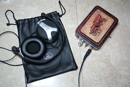 -My AKGs along on their holder plugged in to the amp. 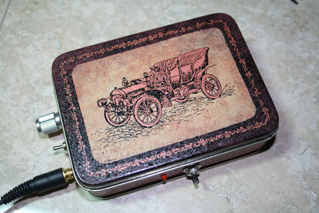 -top of the amp, covered. 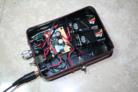 The batteries provide power, where you can see the switch and LED (on). It's orange. Then of course you have the power caps (black and gold), but the tiny resistors are hidden. The top jack is the input jack. There's a ground wire leading to the case coming from the top terminal. The signal goes to the volume control (pot), which is 10k. It goes to the larger film caps, with an F3 of ~5.4hz. The opamp receives the signal, then the output runs to the headphones and either through the feedback resistors only (you can barely see a small blue resistor by the top input cap to the left) or also through the RC circuit depending on the switch position. The blue caps are the feedback caps (.1uf) which are hiding the resistors due to the tiny size. It works just like I expected (I measured) and the bass boost starts at 3dB from 130hz, then gradually increases until 21hz, where the boost is 16dB. 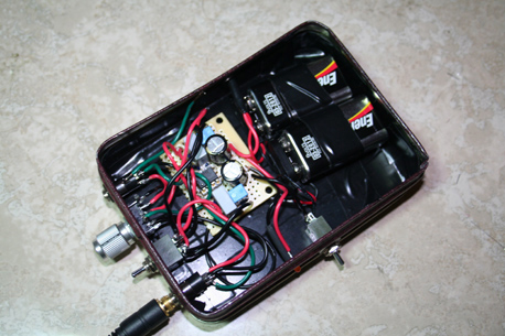 Another angle. And yes, I'm quite happy with the sound. |
|
Platinum Member Username: Jan_b_vigneDallas, TX Post Number: 12874 Registered: May-04 | . It looks good, Andre. You did a nice job. |
|
Silver Member Username: MagfanUSA Post Number: 307 Registered: Oct-07 | Well done, Andre. Great case and packaging, too! Enjoy your new toy. |
|
Platinum Member Username: NuckPost Number: 10598 Registered: Dec-04 | Nice case, Andrew. Well done, and keep on learning and reading, I will be calling you for info soon! Jamie |
|
Platinum Member Username: NuckPost Number: 10599 Registered: Dec-04 | Now we have to insulate the inside of the lid with some.... To control the tendancy of the.. to... Kidding! |
|
Gold Member Username: Arande2Rattle your ... Missouri Post Number: 2918 Registered: Dec-06 | Haha thanks guys it was a good first project. I wonder what's next.. |
|
Gold Member Username: Mike3Wylie, Tx USA Post Number: 1395 Registered: May-06 | Next!!!!! You can't be done tweakin this one yet.... |
|
Gold Member Username: Arande2Rattle your ... Missouri Post Number: 2919 Registered: Dec-06 | Well I'll probably add a DC jack eventually, but that's about it |
|
Gold Member Username: Arande2Rattle your ... Missouri Post Number: 2928 Registered: Dec-06 | It looks like I'm going to have to take the board out of the case today and reflow the solder joints around the left channel's feedback cap. The bass boost switch acts like a gain switch with the left channel since the cap isn't connecting through and only the resistor is in the feedback path. |
|
Platinum Member Username: Jan_b_vigneDallas, TX Post Number: 12932 Registered: May-04 | . Retouch all the connections while you have it out of the case. |
|
Gold Member Username: Arande2Rattle your ... Missouri Post Number: 2929 Registered: Dec-06 | Yeah I did it |
Main Forums
Today's Posts- Home Audio Forum
- A/V Receivers Forum
- Amps Forum
- Cassette Forum
- CD Players Forum
- CD Recorders Forum
- DAC & Transports Forum
- DVD-Audio & SACD Forum
- Equalizers Forum
- Integrated Amps Forum
- iPod Docks Forum
- MiniDisc Forum
- Mini Systems Forum
- Digital Music Systems Forum
- Phono Forum
- Preamps Forum
- Speakers Forum
- Subwoofers Forum
- Tuners Forum
- Home Video Forum
- Home Theater Forum
- Car Audio Forum
- Accessories Forum
- All Forum Topics