I have a VIZO VO37L LCD HDTV with the following symptoms: -No picture, -No Backlight, -Audio Good, -Turns ON and OFF -VIZIO Logo Amber when OFF, WHITE when ON
-After reading many posts about the VX37L, I read a post that indicated that U33 was bad and causing the picture to have no output. The post identifies the bad component as a 3.3V regulator with PartNumber: AMC1117.
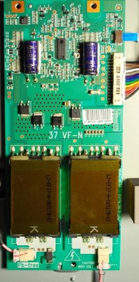
-I also read posts that indicated that the backlight Inverter circuit/board may be the problem when the symptoms include no backlight.
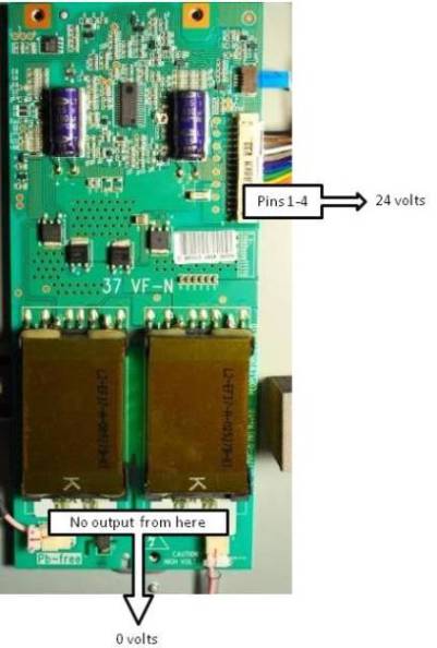
-I took some readings and found the follow results: 1. All Fuses on the Main Board (MB) and Power Supply (P/S) boards are Good. 2. Pins 1-5 on the Inverter Board read 24V - Good.
3. The other posts I was reading were talking about VIZIO Model VX37L and I have a VO37L. I noticed that the components on my MB did not have the same designations (names) as the VX37L.
The following data is from one of the posts: CHIP Vin Vout Adj/Gnd U7 3.30 1.28 0.0 U9 3.30 1.52 0.0 U33 5.19 3.30 2.0 U8 5.19 3.30 2.0 U2 5.19 3.30 2.0 U4 5.19 3.30 2.0
U33 was indicated as the bad component. U33 on the VX37L is a 3-pin voltage regulator. U33 on the VO37L (my TV) is a 8-pin IC chip.
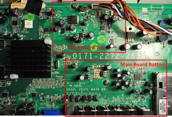
My MB looks like this:
Notice I have marked the top section and Bottom section with RED boxes.
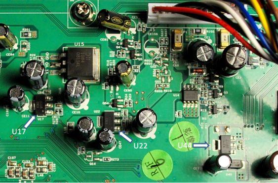
Here is a closeup of the top section showing the names of the AMC1117 voltage regulators on my board.
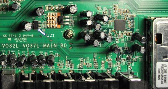
Here is a closeup of the bottom section showing the names of the AMC1117 voltage regulators on my board.
I am trying to identify which component on the VO37L is equivalent to U33 on the VX37L MB.
Here are the voltage readings from my AMC1117 regulators: CHIP Vin Vout Adj/Gnd U22 5.07 3.31 2.08 U17 5.02 3.33 2.09 U44 11.83 9.57 8.34 U21 1.24 2.50 0.0
The voltages on my U44 seem to be WAY OFF so I am thinking this is the equivalent to the U33 regulator??
Any thoughts or ideas? I have already ordered 3 AMC1117 regulators and plan to replace U44.
Is anybody out there? I was hoping that someone could help answer my question posted above!! I have received my AMC1117 regulators but still do not know which regulator is the equivalent to U33. My board doesn't have the same numbering sceme as the VX37L board.
Can someone look at the pictures I posted and let me know whick of my 3.3 V regulators is the "U33" equivalent?
Last night, I replaced two of the 3.3V regulators on my Main Board, U44 and U21. I picked these two since the voltages were different from all the others. Anyway, after replacing each regulator, I checked the functionality of the TV and the voltages on the regulators and there was no change! This means that these components were not the problem.
I hooked up an older DVD that I had lying around to the AV2 Input and although I still had a black/blank screen, I did have good audio output. I read in another post that you can shine a bright light onto the screen and if there is video output you will be able to see shadows and movement. I did this and I was able to see video on the screen. So, at this point I monitored some voltage inputs and outputs on the inverter board and although I had good 24V input power, there was basically Zero volts on the outputs of the transformers that feed the wires that connect to the backlight. I am fairly certain now that my problem is the inverter board and NOT the main board or power supply.
I ordered a new inverter board from TVPartsPlus.com for $63.00. I will post the results when I replace this board.
Hi Dave, Sounds like your on the right track. Without the schematics of the boards is hard to tell you which parts from one board are equal to the circuits on another board. Its worth the $63 investment in the inverter board I think. Good luck and Happy Holidays. Mike G.
Thanks Mike, It seems that the problem is either the inverter board or quite possibly the backlight itself. How can you check the backlight? Can you measure the resistance across the filaments? Is there a way to troubleshoot (T/S) to determine if it is an inverter board or a backlight issue?
mine seems sensitive to touching J2 on main board.... i can force pson and get 24 volts to inverter boards but they dont make high voltage until the main board tells them to, I THINK....
odd- i unplugged and re-plugged J2, the cable to the pushbuttons, it clicked and ran for about ten minutes.
Good job to you too old jim... sounds like you've got it fixed. Post back in a week or so and let us know how it's working. This is an important post because it shows an example of two TVs with VERY similar symptoms each with a different failed board and repair. It's important when troubleshooting not to jump to conclusions when trying to determine the problem. It's a big waste of time and money to just start replacing boards and components without really knowing for sure what the problem is... we call that "Easter Egging" (hunting for eggs - hunting for the problem). Sometimes (after doing all the normal/proper troubleshooting steps) you are left with no choice but the process of elimination and you have to start replacing things. I think most of us on this forum are just regular guys (not trained electronics techs using schematics) and so sometimes we have to do what we have to do...
Dave, The thing you have to look for when checking the regulators and/or the inverters is the BL on pulse (Backlight on). Based on your picture above, it should be the black wire at the very top. That plug will have multiple lines with 24VDC, and depending on which variant a BL on and (not all) a dimming pulse. The BL on is what tells the inverter to turn on. It should read somewhere between 2.5 and 5 VDC.
On the models that have the regulator problems, this pulse is missing. All of your regulators had a normal reading. Those regulators are what is called a "variable regulator". This means they regulate the out put based on the input and the ground/adj. If the adjust is at ground potential then the output will be a very small percentage of the input. As the potential rises on this pin, and larger percentage of the input is passed to the output side.
Hope this helps,,, and remember to check the 2 electrolytic capacitors on your replacement inverter. If you ordered a pulled inverter, these caps fail and lead to a total inverter failure.
Mine is still fixed. Well actually it is Daughter's.
She had it diagnosed by a shop and was told it needed the two high voltage backlight boards for ~$800.
What i found was on main board there's a signal called PSON presumably means Power Supply On
when i pushed PSON line "HIGH" with ohmmeter it caused all the power supplies to turn on, both the lv(12, 24 and 5) and the hv ones on each side ... so i figured somethaing was not telling power supplies when it was time for them to come on
PSON is generated by the two tiny transistors between U15 and red wire in your excellent photo above. They are slaved to a small IC several inches away by a long serpentine track connecting them. You can follow it visually from base of inboard transistor. That IC has leads on all four sides, must be fifty of them, so there's no way to troubleshoot further with just a meter . Had that IC directed those two transistors to assert PSON i'd have had power supply voltage, but when i forced it and supplies came on there was still no picture. So i figured it's computer trouble and blamed Bill Gates. ..
Accordingly i took a chance and ordered a replacement main board. $150 including shipping from that outfit in Atlanta.
ps i too had chased around those same regulators but was unable to conclude anything. PSON line interacts with them if i recall right, so i went looking for its source.
First you need to disconnect the inverter board. only hook up the power supply and the main board. Then check the PSON on the power supply is getting power..about 3.3V. The PSON pin is labeled and located on the right side of the power supply board with all the connectors.
Next, if you have pson at 3.3V then check that there is voltage at the 12V and 24V of the power supply.
If this is ok then you connect the inverter board. Then check the 12V and 24V again. This may change.. which was what the problem was with my TV.
I had to remove one of the big caps to get the TV screen back on. It seems that the TV is working again.. not sure how long this will last though.
I seem to be having a common problem..black screen on my vizio, I do have audio and I can also change channels ( I can tell by the audio sounds)There were two 'popping' noises ..the TV went blank right after the 1st 'pop'
The only thing I can see looking into the back of the TV are two small 'green lites"
where do I begin???? I will have to utilize my neighbor to check voltage(s) if I need to.
I have Lg 47LX9900 the Backlight On signal is 00V on PSU. I checked PSU without connecting it to mainboard and it turned on the backlight. So there is no signal from main av board to psu to turn on the Backlight or Invertor. How to enable this signal?